
User Manual


Apollo3 Blue Datasheet
DS-A3-0p9p1 Page 570 of 909 2019 Ambiq Micro, Inc.
All rights reserved.
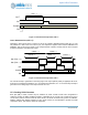
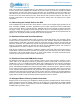
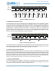
EN is used to enable (when 1) and disable (when 0) the counting function of the CTIMER. However, EN
and the deassertion of CLR are synchronized to the selected clock, which must be accounted for when
they are used. CLR and EN Operation shows how this synchronization occurs. When CLR is set to 0, the
Counter will begin counting on the second edge of the selected clock if EN is set to 1. When EN is set to 0,
the Counter will increment on the next clock (from 1 to 2 in CLR and EN Operation) and then hold its
current value. When EN is set to 1, the Counter will resume counting on the second following edge.
Figure 82. CLR and EN Operation
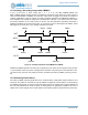
Since the operation of the processor is essentially asynchronous to the selected clock, the synchronization
introduces an uncertainty as to when the Counter will begin counting. If the frequency of the selected clock
is high relative to the processor clock, the impact of the synchronization will be negligible. However, for low
frequency clocks, external pin clocks and the buck clocks the effective delay caused by the
synchronization may be significant.
13.17NOSYNC Function
Under normal conditions, the CTIMER clocks are supplied directly by the clock selected in the
REG_CTIMER_CTCTRLx_TMRxyCLK register field. However, if software reads the TMR value the clock
will be temporarily synchronized to the processor clock, which may cause the time of edges on an output to
move slightly. The time of any edge will be moved by at most 20 ns from the normal time. If this variation is
unacceptable for a specific application, it can be eliminated in one of two ways:
1. Do not read the TMR value during the output generation. This is often an acceptable restriction.
2. Set the REG_CTIMER_CTAUXxy_NOSYNC register bit. This will disable the synchronization func-
tion.
If the NOSYNC bit is set, the TMR update will no longer be synchronized to the processor clock. As a
result, the TMR value read might be incorrect. In this case, software should read the TMR three times in
quick succession (with interrupts disabled) and determine the correct value from those. If the first two
reads are the same, that is the correct value. If they are different, the third value is correct.
13.18Counter Functions
A CTIMER operates in Counter mode when the TMRxyCLK field selects either the external pad input (if
0x00) or a buck pulse input (if 0x10). Although any of the modes may be selected, the typical configuration
is Continuous. In this mode the CTIMER will count edges on the selected clock, and may be configured to
generate an interrupt on a particular count value. The different clock selections provide different functions.
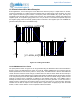
13.18.1Counting External Edges
If the CLK field is 0x00, the CTIMER clock input comes from an external pad as selected by the INCFG
register. This allows the CTIMER to monitor pulses or edges on an external signal.
N
Clock
Counter
N + 1
CLR
0
EN
1 2 3