
User Manual


Apollo3 Blue Datasheet
DS-A3-0p9p1 Page 569 of 909 2019 Ambiq Micro, Inc.
All rights reserved.
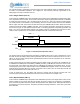
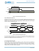
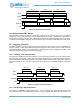
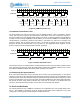
Figure 80. PWM-based Pulse Train
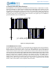
13.15.2Pattern-based Pulse Trains
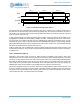
The pulse patterns may also be generated using the Repeated Pattern function described in Section
13.2.6. This is shown in Figure 81, and assumes the same pattern as the one in Figure 80. However, in
this case the first N bits of the desired pattern (where N can be 64 or 128) are loaded into the CMPR0/1/2/
3 registers of either a single CTIMER (for 64-bit patterns) or the A and B CTIMERs of a CTIMER pair (for
128-bit patterns). A full pattern consists of both Pattern 1 and Pattern 2 in Figure 81, for example. The
process is started, and an interrupt will occur after ½ of the first full pattern (32 or 64 bits) has been
generated. At that point software loads a new ½ pattern into the appropriate CMPR registers, and the
process continues until the complete pattern has been generated.
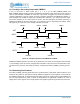
Figure 81. Pattern-based Pulse Train
The selection of 64-bit vs. 128-bit patterns is a tradeoff between power (the longer pattern results in half as
many interrupts) and resource usage (the longer pattern requires two CTIMERs instead of one). If there
are sufficient CTIMERs available, the 128-bit pattern is always more efficient.
13.15.3Selecting the Optimal Method
Both of the above approaches produce the same result in terms of the generated pattern, so the optimal
selection is a function of minimizing the number of interrupts required to produce the overall pattern. Fewer
interrupts result in longer CPU sleep times and less interrupt servicing overhead, which reduces the overall
power. If the half pattern can cover more time than the average PWM Period, the Pattern-based approach
will typically be more energy efficient. Whether this is the case is a function of the desired fast clock
frequency, which determines the precision of the pulses, and the desired pulse lengths.
13.16CLR and EN Details
The overall operation of each CTIMER is controlled by two configuration bits, CLR and EN. When CLR is
set to 1, the CTIMER is immediately set to all zeroes and will remain there independent of any other
configuration. CLR is typically used to initialize a CTIMER before use.
Fast_clk
PWM Out
PWM Period PWM Period PWM Period PWM Period PWM Period PWM Period PWM Period PWM Period
CMPR1
CMPR0
+ Intrpt
CMPR2
+ Intrpt
CMPR3 CMPR1
CMPR0
+ Intrpt
CMPR2
+ Intrpt
CMPR3 CMPR1
CMPR2
+ Intrpt
CMPR3
CMPR0
+ Intrpt
CMPR1
CMPR2
+ Intrpt
CMPR3
CMPR0
+ Intrpt
Fast_clk
PWM Out
Pattern 1 Pattern 2 Pattern 3 Pattern 4
INT INT INT