
User Manual


Apollo3 Blue Datasheet
DS-A3-0p9p1 Page 568 of 909 2019 Ambiq Micro, Inc.
All rights reserved.
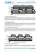
13.15Pattern-based Sine Wave Examples
Some applications, such as driving the Linear Resonance Actuator (LRA) in a Haptic Driver or vibrator,
require the generation of a pattern which is integrated into an analog signal, most commonly as a sine
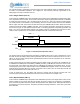
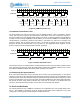
wave. Figure 79 shows the typical function. The square pulses have variable duty cycles, and they are
integrated by the external device to produce the sine wave. The external device typically has positive and
negative inputs, so the positive-going pulses occur on a pin which is connected to the positive input and
the negative-going pulses are actually positive pulses connected to the negative input. The CTIMER can
generate these pulse trains in two different ways.
Figure 79. Creating a Sine Wave
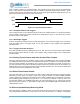
13.15.1PWM-based Pulse Trains
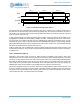
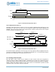
The pulse patterns shown in Figure 79 can be generated using the Alternate Pulse function described in
Section 13.2.8. The PWM pulses are shown in Figure 80. Initially CMPR0/1/2/3 are configured with the
desired parameters for the first two pulses. In many cases, the PWM Period is fixed so that CMPR1/3
contain the same value and never change, but these times can also be varied. When the first interrupt is
received at the end of first CMPR0 period, software will update the CMPR0 register with the value required
in the next period (and would also update CMPR3 with the next value if it should change). When the next
interrupt is received at the comparison to CMPR2, a new CMPR2 value (and a new CMPR1 value if
desired) are loaded. This process proceeds throughout the cycle which generates ½ of the sine wave. A
similar process is repeated for the negative output to produce the second ½ of the sine wave. Note that
software must be able to respond to the interrupt within a period which is slightly longer than the PWM
Period, in order to insure that the correct comparison values are loaded.
ysinx,x∊0,2π
y‐sinx,x∊0,2π
O
1
-1
π/2 π
2π
3π/2
y
x