
User Manual


Apollo3 Blue Datasheet
DS-A3-0p9p1 Page 567 of 909 2019 Ambiq Micro, Inc.
All rights reserved.
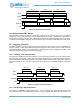
mode. Two counters are configured with FN = 6 so that they count continuously. One is supplied HCLK as
its clock, and the other is supplied with a divided version of the HFRC clock. The two counters are enabled
simultaneously, and after some period of system operation they are disabled and read. The HFRC count
value defines how much real time has elapsed and how many HCLKs could have occurred in that time,
and the HCLK count value defines how many actual HCLKs were received in that time. The ratio is an
accurate measurement of the percentage of time the CPU is asleep, and is an effective tool for power
optimization.
13.11Generating the Sample Rate for the ADC
Timer CTTMRA3 has a special function which allows it to function as the sample trigger generator for the
ADC. If the REG_CTIMER_ CTCTRL3 _ADCEN bit is set, the output of the timer is sent to the ADC which
uses it as a trigger. Mode 1 is typically selected. TMRA3IE may be set to generate an interrupt whenever
the trigger occurs, but typically the ADC interrupt will be used for this purpose.Typically, Ctimer3 is
configured in Repeated Count (FN =1) mode. TMRA3IE may be set to generate an interrupt whenever the
trigger occurs, but typically the ADC interrupt will be used for this purpose.
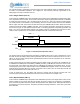
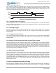
13.12Software Generated Serial Data Stream
It is possible to use the Repeat Pattern mode to produce a serial data stream, such as PDM. A Timer/
Counter would be configured to use an external pad as the clock. Software would load the CMPR0/1/2/3
registers with the first 64 bits of the pattern. When the secondary interrupt is received, the first 32 bits will
have been transferred, and software can load the next 32 bits into CMPR0/1. When the next secondary
interrupt is generated, software can load the next 32 bits into the CMPR2/3 registers, and continue to
toggle between the two pairs of registers. This can continue indefinitely.
Note that the requirement for software to update the registers continuously will require the processor to
remain awake, unless the transfer is quite slow. For example, if the clock frequency were 1 MHz, software
would have to load a 32-bit register every 32 us, which would probably not support a wakeup interrupt.
However, at lower frequencies this could be a useful function.
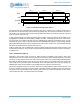
13.13Software Generated PWM Audio Output
The Alternate Pulse mode can be used to efficiently create an audio output stream in software. In many
cases, audio can be effectively produced by generating a stream of pulses with a fixed period, but a
variable duty cycle (i.e. a variable pulse width). When this is applied through a low pass filter, reasonable
audio output will result. In Alternate Pulse mode, CMPR1 and CMPR3 are set to the desired sample
period, and CMPR0 and CMPR2 are configured with the widths of the first two pulses. When the interrupt
occurs at the end of the period, software loads CMPR0 with the next pulse width. When the next interrupt
occurs, software loads CMPR2 with the next pulse width, and toggles between the two registers for each
subsequent pulse. Because the sample rate of audio is often quite slow, software can generally handle this
process in an interrupt driven fashion. When the interrupt occurs, there is a full sample period before new
register data is needed, so that the interrupt service requirement is easy to achieve.
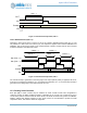
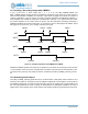
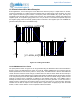
13.14Stepper Motors Driven by Pattern Generation
Stepper motors can be driven by the CTIMERs by utilizing the pattern generation feature. Some of the key
pattern generation features are arbitrary patterns up to 128 bits long, synchronization of multiple CTIMER
pattern generation outputs, and the ability to use another CTIMER to generate the pattern clock base for
CTIMER pattern generation output.