
User Manual


Apollo3 Blue Datasheet
DS-A3-0p9p1 Page 566 of 909 2019 Ambiq Micro, Inc.
All rights reserved.
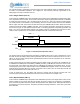
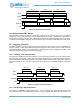
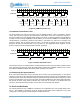
burst of pulses or patterns of a specified length. This is shown in Figure 78 for the case of Repeat Pulse
mode. In this case the TRIG signal is the output of a TIMER configured in Single Pulse mode (FN = 2) with
the time configured to be somewhat more than 3 times the pulse repeat. When the TRIG signal occurs, the
pulse output is terminated at the end of the current cycle.
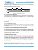
Figure 78. Terminated Repeat Patterns
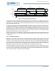
13.7.3 Complex Patterns with Triggers
The two trigger modes can be combined to produce even more complex patterns. As a particular example,
the OUT signal of Figure 78 could be selected as the TRIG signal in Figure 77. This would then produce
exactly four bursts of the pattern.
13.7.4 Dual Edge Triggers
Some of the trigger input selections specify dual edge triggers. In that case, the trigger occurs on both the
rising and falling edge of the trigger signal. This is very valuable in some stepper motor applications
described below.
13.7.5 Trigger Controlled Inversion
If the REG_CTIMER_CTAUXxy_TMRxyTINV bit is set, both the OUT and OUT2 outputs will be XORed
with the trigger signal selected by TRIG. This enables some complex stepper motor configurations
described below.
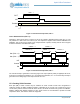
13.8 Clocking Timer/Counters with Other Counter/Timer Outputs
There are cases where it is very valuable to use the output of a CTIMER as the clock of another CTIMER.
The TMRxyCLK field includes choices which implement this function, in addition to the normal clocks taken
from the internal oscillators. An example of such a function is the terminated count shown in Figure 78. If
the clock of the timer which produces the TRIG signal were taken from the OUT output of the first timer, the
CMPR0 value used for the trigger generator would be trivially calculated as 2, and would be independent
of the actual clock used to generate the OUT signal.
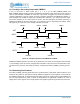
13.9 Global Timer/Counter Enable
There are times when it is very important to be able to start multiple Timer/Counters precisely together,
particularly in cases where one output is used as the trigger of another. The REG_CTIMER_GLOBEN
register contains one enable bit for each Timer/Counter, which is ANDed with the local EN bit of the timer.
The GLOBEN register normally has all bits set to 1, so that the local EN bits control the timers. For
synchronized enabling, the GLOBEN register bits to be synchronized are set to 0, and then the local EN
bits of those timers are set to 1. At that point a single write to the GLOBEN register will enable all of the
selected timers at once.
13.10Power Optimization by Measuring HCLK
Each timer has the capability to select the processor clock HCLK as the counter clock input. This allows a
very straightforward measurement of how much of the time the processor is in a Sleep or Deep Sleep
OUT
TRIG
EN