
User Manual


Apollo3 Blue Datasheet
DS-A3-0p9p1 Page 565 of 909 2019 Ambiq Micro, Inc.
All rights reserved.
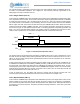
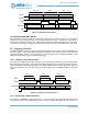
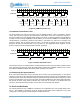
Figure 76. Dual Pattern Generation
13.6 Synchronized A/B Patterns
If the CTLINK bit is set for the B timer of a pair when a Pattern mode is selected (FN = 4 or 5), the pattern
comparison value is taken from the A Counter rather than the B Counter. This allows the generation of
dual up to 64-bit patterns using the OUT outputs of both the A and B Timers with EN23 clear in both cases,
or quad up to 32-bit patterns using the OUT and OUT2 outputs of both timers with EN23 set in both cases.
13.7 Triggering Functions
The REG_CTIMER_CTAUXxy_TRIG field allows the specification of the output of another CTIMER to be
used as a trigger. There are several areas where the trigger function may be used to create extremely
sophisticated pattern outputs. If the TRIG field is 0, the triggering function is disabled. Otherwise, TRIG
selects the internal timer output to be used as the trigger.
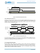
13.7.1 Initiating a One-shot Operation
If the mode of a CTIMER is a one-shot mode (FN = 2 or 4), when EN is asserted one cycle of the operation
will be executed. At that point, a rising edge on the trigger signal selected by TRIG will cause the operation
to be executed again. This allows the creation of complex operations with a single configuration. Figure 77
shows an example of this. The TRIG signal is the OUT signal from a CTIMER configured for Repeat
Count.
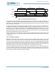
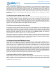
Figure 77. Triggered One-Shot Patterns
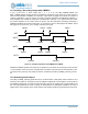
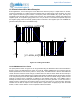
13.7.2 Terminating a Repeat Operation
If the mode of a CTIMER is a repeat mode (FN = 1, 3 or 5), the rising edge of the TRIG signal will cause
the repeated operation to terminate after the current cycle is complete. This allows the easy creation of a
OUT
INT
Counter
EN
0 Incrementing 0
LMT + 1 LMT + 1 LMT + 1
Incrementing 0 Incrementing 0 Inc
PATTERN01 PATTERN01 PATTERN01
OUT2
PATTERN23 PATTERN23 PATTERN23
OUT
TRIG
Counter
EN
0 Incrementing 0
LMT + 1 LMT + 1 LMT + 1
Incrementing 0 Incrementing 0
PATTERN PATTERN PATTERN