
User Manual


Apollo3 Blue Datasheet
DS-A3-0p9p1 Page 564 of 909 2019 Ambiq Micro, Inc.
All rights reserved.
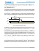
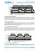
13.4 Creating a Secondary Output with CMPR2/3
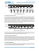
In any of the Count or Pulse modes (FN = 0, 1, 2 or 3), the REG_CTIMER_CMPR2 and
REG_CTIMER_CMPR3 registers provide two additional comparison points. When the counter reaches a
value in either CMPR2 or CMPR3, the secondary output OUT2 is toggled. This allows the creation of
complex combinations of the two outputs, as shown in Complex Operations with CMPR2 and CMPR3. In
these examples, the CTIMER is configured in repeated pulse mode (FN = 3) to produce the OUT output,
and several variations of the output OUT2 are shown. The third example is particularly interesting. If
CMPR2 and CMPR3 are set to the same value, or one of them is set to a value larger than CMPR1, OUT2
will toggle only once per OUT cycle, creating a divide-by-two signal.
Figure 75. Complex Operations with CMPR2 and CMPR3
CMPR2 and CMPR3 operate in the same way for pulse and count modes. Thus in Single Count mode (FN
= 0) for example, OUT2 can produce a single pulse or transition at any time prior to the termination of the
count when OUT goes high. The polarity of OUT2 is controlled by the REG_CTIMER_CTAUXxy_POL23
bit.
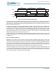
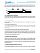
13.5 Generating Dual Patterns
If the REG_CTIMER_CTAUXxy_EN23 bit is set in a Pattern Mode, a dual pattern will be created on OUT
and OUT2. The pattern on OUT will use only the CMPR0/1 register bits, and the pattern on OUT2 will use
the CMPR2/3 register bits, so that the longest dual pattern that can be created from a single CTIMER is 32
bits. The output patterns are shown in Figure 76. Dual patterns are particularly valuable in the case of
stepper motor control signals, which require positive and negative signals to be generated synchronously.
OUT
OUT2
CMPR0 CMPR1 CMPR0 CMPR1
CMPR2 CMPR3 CMPR2 CMPR3
OUT2
CMPR2 CMPR3 CMPR2 CMPR3
OUT2
CMPR2/3 CMPR2/3