
User Manual


Apollo3 Blue Datasheet
DS-A3-0p9p1 Page 563 of 909 2019 Ambiq Micro, Inc.
All rights reserved.
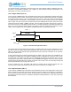
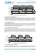
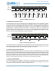
Figure 73. Counter/Timer Operation, FN = 4
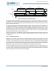
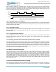
13.2.8 Alternate Pulse (FN = 7)
Operation in this mode is shown in Figure 74, and is very similar to Repeated Pulse mode (FN = 3). The
only difference is that at the end of each cycle, the comparison register switch between CMPR0/1 and
CMPR2/3. This can be used to create a more complex stream of pulses, and may also be used to support
an efficient software controlled audio output.
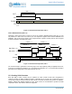
Figure 74. Counter/Timer Operation, FN = 7
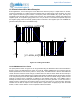
The normal interrupt is generated on the rising edge of the output (before polarity is applied) if IE0 is set,
as shown in Counter/Timer Operation, FN = 7Counter/Timer Operation, FN = 3. The secondary interrupt is
generated on the falling edge of the output if the IE1 bit is set.
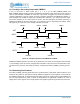
13.3 Creating 32-bit Counters
Each pair (A/B) of 16-bit counters may be combined to create a 32-bit counter. This configuration is
created by setting the REG_CTIMER_CTCTRLx_CTRLINKx bit for the pair. The control bits for the A
counter of the pair are used to control the 32-bit counter, and the B control bits are ignored. The CMPR0 ,
CMPR1, CMPR2 and CMPR3 registers for each 16-bit counter are concatenated to provide the 32-bit
comparison values, and all timer modes are supported.
PATTERN
OUT
INT
Counter
EN
0 INCREMENTING 0
LMT + 1
Out (POL = 0)
Out (POL = 1)
INT
Counter
EN
0 Incrementing 0
~CMPR0 + 2
~CMPR1 + 2
CMPR2 + 1
CMPR3 + 1
Incrementing 0 Inc
CMPR0 + 1