
User Manual


Apollo3 Blue Datasheet
DS-A3-0p9p1 Page 562 of 909 2019 Ambiq Micro, Inc.
All rights reserved.
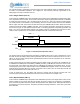
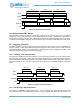
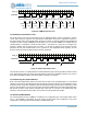
Figure 72. Counter/Timer Operation, FN = 5
The primary interrupt is generated when the pattern rolls over to 0 (if IE0 is set). If LMT is greater than 31
and less than 63, the secondary interrupt will be generated when the Counter increments to 32 (if IE1 is
set). If LMT is 63, the secondary interrupt will be generated both when the Counter increments to 32, and
when the Counter rolls over to 0.
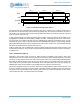
If LMT is greater than 63, the pattern generation will use 128-bit mode. This mode is only available for the
A CTIMER of a CTIMER pair, and the REG_CTIMER_CTCTRLx_CTRLINKx bit must be set. In this mode,
the first 64 bits of the pattern are taken from the CMPRA0/1/2/3 registers as described above, and the
remaining bits (up to a total of 128) are taken from the CMPRB0/1/2/3 registers. The secondary interrupt
will be generated when the Counter increments to 64 (if IE1 is set). If LMT is 127, the secondary interrupt
will also be generated when the Counter rolls over to 0.
If LMT is greater than 127, the pattern will continue to repeat until the Counter reaches LMT, and then it will
repeat from the beginning. The secondary interrupt will be generated each time the Counter increments to
a multiple of 64.
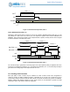
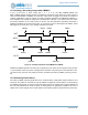
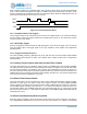
13.2.7 Continuous (FN = 6)
Operation in this mode is shown in Figure 73. When the Timer is enabled, the pin output is at the level
selected by the POL bit and the Timer is at zero because CLR has been asserted previously. The Timer
counts up on each selected clock, and when it reaches the value in the corresponding CMPR0 Register
the output pin switches polarity (if the PE bit is set) and an interrupt is generated (if the IE bit is set). The
Timer continues to count and is never automatically reset. If the Timer rolls over to zero and reaches the
CMPR0 value again, an interrupt will not be generated and the output pin will not change.
This mode is primarily used for two functions. The first is counting transitions on the external input pin, and
it may be valuable to generate an interrupt when a specified number of transitions have been detected.
The second is as a general timer which software reads in order to measure time periods. In this second
case an interrupt is often not used and will not be enabled.
OUT
INT
Counter
EN
0 Incrementing 0
LMT + 1 LMT + 1 LMT + 1
Incrementing 0 Incrementing 0 Inc
PATTERN PATTERN PATTERN PAT