
User Manual


Apollo3 Blue Datasheet
DS-A3-0p9p1 Page 561 of 909 2019 Ambiq Micro, Inc.
All rights reserved.
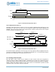
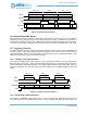
The normal interrupt is generated on the rising edge of the output (before polarity is applied) if IE0 is set,
as shown in Counter/Timer Operation, FN = 3Figure 70. The secondary interrupt is generated on the
falling edge of the output if the IE1 bit is set.
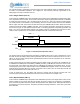
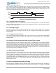
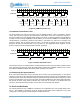
13.2.5 Single Pattern (FN = 4)
In this mode the CTIMER outputs are generated from the pattern in the CMPR0/1/2/3 registers rather than
from comparisons to the Counter. The Counter is still used to step through the pattern bits. Bit 0 of CMPR0
is output when the Counter is 0, bit 1 is output when the Counter is 1, and so on until the Counter reaches
16. At that point bit 0 from CMPR1 is output. Similarly, when the Counter reaches 32 the bits from CMPR2
will be output, and when the Counter reaches 48 the bits from CMPR3 will be output. When the Counter
reaches the limit set by REG_CTIMER_CTAUXxy_LMT, the pattern generation stops and OUT returns to
0 as shown in Figure 71. Note that this results in LMT + 1 bits being generated. The pattern generation will
begin 1 or 2 clock cycles after EN is asserted. The polarity of OUT is controlled by the POL bit as in other
cases. If LMT is greater than 127, the pattern will repeat until LMT is reached and then stop.
Figure 71. Counter/Timer Operation, FN = 4
The primary interrupt is generated when the pattern completes if IE0 is set. If LMT is greater than 31 and
less than 63, the secondary interrupt will be generated when the Counter increments to 32 if IE1 is set. If
LMT is 63, the secondary interrupt will be generated both when the Counter increments to 32, and when
the Counter rolls over to 0.
If LMT is greater than 63, the pattern generation will use 128-bit mode. This mode is only available for the
A CTIMER of a CTIMER pair, and the REG_CTIMER_CTCTRLx_CTRLINKx bit must be set. In this mode,
the first 64 bits of the pattern are taken from the CMPRA0/1/2/3 registers as described above, and the
remaining bits (up to a total of 128) are taken from the CMPRB0/1/2/3 registers. If IE1 is set, the secondary
interrupt will be generated when the Counter increments to 64. If LMT is 127, the secondary interrupt will
also be generated when the Counter rolls over to 0.
If LMT is greater than 127, the pattern will continue to repeat until the Counter reaches LMT. The
secondary interrupt will be generated each time the Counter increments to a multiple of 64.
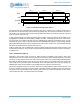
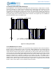
13.2.6 Repeat Pattern (FN = 5)
In this mode the CTIMER outputs the pattern from CMPR0/1/2/3 just as in the Single Pattern case, but the
pattern repeats as soon as the LMT value is reached, as shown in Figure 72. The polarity is controlled by
POL, and if LMT is greater than 63 the pattern will repeat within each pattern burst, although it will restart at
the beginning once LMT is reached. The pattern generation will begin between 1 and 2 clock cycles after
EN is asserted.
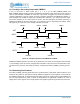
PATTERN
OUT
INT
Counter
EN
0 INCREMENTING 0
LMT + 1