
User Manual


Apollo3 Blue Datasheet
DS-A3-0p9p1 Page 559 of 909 2019 Ambiq Micro, Inc.
All rights reserved.
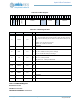
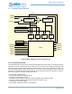
13.2.2 Repeated Count (FN = 1)
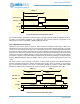
Operation in this mode is shown in Figure 68. When the Timer is enabled, the pin output is at the level
selected by the POL bit and the Timer is at zero because REG_CTIMER_TMRxyCLR has been asserted
previously. The Timer counts up on each selected clock, and when it reaches the value in the
corresponding CMPR0 Register the output pin switches polarity (if the REG_CTIMER_TMRxyPE bit is set)
and an interrupt is generated (if the IE bit is set). At this point the Timer resets to 0 and the output pin is
maintained at the selected level for one clock cycle, after which it returns to the original value. The Timer
continues to count up and the process is repeated, creating a stream of pulses or interrupts at a fixed
interval. The interrupt may be cleared by writing the corresponding WC bit in the TMRWCR Register at any
point prior to the next setting pulse.
If the REG_CTIMER_TMRxyEN bit is cleared, the Timer will stop counting but will not be cleared, so the
sequence may be paused and then resumed. Setting CLR will reset the Timer to zero. Note that CMPR0
must be at least 1 so that the repeat interval is two clock cycles.
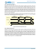
Figure 68. Counter/Timer Operation, FN = 1
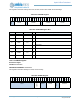
13.2.3 Single Pulse (FN = 2)
Operation in this mode is shown in Figure 69. When the Timer is enabled, the pin output is at the level
selected by the REG_CTIMER_TMRxyPOL bit and the Timer is at zero because CLR has been asserted
previously. The Timer counts up on each selected clock, and when it reaches the value in the
corresponding CMPR0 Register the output pin switches polarity (if the REG_CTIMER_TMRxyPE bit is set)
and an interrupt is generated (if the REG_CTIMER_TMRxyIE bit is set). At this point the Timer continues to
increment and the output pin is maintained at the selected level until the Timer reaches the value in the
CMPR1 Register, at which point it switches back to the original level. This allows the creation of a pulse of
a specified width. The Timer is reset to 0 so that a single pulse is created. The interrupt may be cleared by
writing the corresponding WC bit in the TMRWCR Register.
Out (POL = 0)
Out (POL = 1)
INT
Counter
EN
0 Incrementing 0
~CMPR0 + 2 CMPR0 + 1 CMPR0 + 1
Incrementing 0 Incrementing 0 Inc