
User Manual


Apollo3 Blue Datasheet
DS-A3-0p9p1 Page 558 of 909 2019 Ambiq Micro, Inc.
All rights reserved.
▪ Generate outputs triggered or terminated by outputs of other Timer/Counters
▪ Generate a specified number of patterns
▪ Special inversion functions to support bidirectional stepper motor patterns
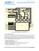
13.2 Counter/Timer Functions
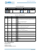
Each Counter/Timer operates in a mode controlled by the REG_CTIMER_CTCTRLx_TMRxyFN bit field
(x=0 to 7, y=A or B). The mode affects both the generation of interrupts and the control of the outputs.
Each mode is described in the following sections. Note that for all functions except for Pattern Generation,
a REG_CTIMER_CMPR0/1/2/3 value of zero (a count of 1) is invalid, and that the first measured period
will be between the REG_CTIMER_CMPR0 value plus 2 and the specified value plus 3. Subsequent
repeated cycles will be correctly of length (CMPR value + 1). There are eight modes:
0 => Single Count: Counts one time to the compare value, then the output changes polarity and stays
at that level, with an optional interrupt.
1 => Repeated Count: Periodic 1-clock-cycle wide pulses with optional interrupts.
2 => Single Pulse (One Shot): A single pulse of programmed width, with an optional interrupt.
3 => Repeated Pulse: A rectangular (or square) waveform with programmed high and low widths, and
optional interrupts on each cycle.
4 => Single Pattern: one burst of bits specified by the CMPR0/1/2/3 registers.
5 => Repeated Pattern: repeated burst of bits specified by the CMPR0/1/2/3 registers.
6 => Continuous: Free running timer with a single level change on the output and a single optional
interrupt.
7 => Alternate Pulse: like Repeated Pulse but alternating between two different pulse width/spacing
settings.
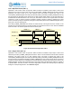
13.2.1 Single Count (FN = 0)
Operation in this mode is shown in Figure 67. When the Timer is enabled, the pin output is at the level
selected by the POL bit and the Timer is at zero because CLR has been asserted previously. The Timer
counts up on each selected clock, and when it reaches the value in the corresponding
REG_CTIMER_CMPR0 Register the output pin switches polarity (if the PE bit is set) and an interrupt is
generated (if the IE bit is set). At this point the Timer resets to 0 and the output pin is maintained at the
selected level until the Timer is cleared with CLR. The interrupt may be cleared by writing the
corresponding WC bit in the TMRWCR Register.
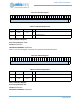
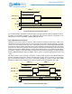
Figure 67. Counter/Timer Operation, FN = 0
Out (POL = 0)
Out (POL = 1)
INT
Counter
EN
0 Incrementing 0
~CMPR0+2