
User Manual


Apollo3 Blue Datasheet
DS-A3-0p9p1 Page 557 of 909 2019 Ambiq Micro, Inc.
All rights reserved.
13. Counter/Timer Module
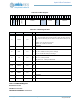
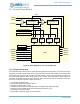
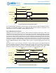
Figure 66. Block Diagram for One Counter/Timer Pair
13.1 Functional Overview
The Apollo3 Blue MCU Timer/Counter module includes eight Timer/Counter pairs, one of which is shown in
Figure 66, as well as a system timer shown in Figure 84 in the System Timer chapter. Each Timer/Counter
pair includes two very low power asynchronous 16-bit counters, which may be combined to provide a 32-
bit counter. Eight registers contain reset values for the counters and/or comparison values to allow the
generation of complex internal and external signals. Each Timer/Counter has an external pin connection,
and can be configured to provide a variety of functions:
▪ Interrupt after a specified delay
▪ Interrupt periodically with a specified period
▪ Determine the time between events
▪ Generate an external pulse of a specified width, configurable after a specified delay
▪ Generate an external PWM signal with a specified period and duty cycle
▪ Count edges on an external input
▪ Interrupt after a specified number of external pulses
16-bit Counter A 16-bit Counter B
TMRPINA
Clk Sources
16-bit Compare0/1/2/3A
16-bit Compare0/1/2/3B
Cmprs Patsel
Control
TMRAOUT
TMRINTA
TMRPINB
Patsel Cmprs
TMRAOUT2
TMRINTB
CLRA
CLRB
TMRBOUT
TMRBOUT2
TMRINTA
TMRINTB
TRIGGERA
TRIGGERB
ConfigurationA
ConfigurationB