
User Manual


Apollo3 Blue Datasheet
DS-A3-0p9p1 Page 523 of 909 2019 Ambiq Micro, Inc.
All rights reserved.
12. Clock Generator and Real Time Clock Module
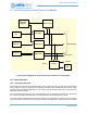
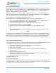
Figure 63. Block diagram for the Clock Generator and Real Time Clock Module
12.1 Clock Generator
12.1.1 Functional Overview
A high-level view of the Clock Generator Module, which supplies all clocks required by the Apollo3 Blue
MCU, is shown in Figure 63. These clocks are derived from one of three fundamental clock sources: a high
precision crystal controlled oscillator (XT), a low power 1 kHz RC oscillator (LFRC) and a high frequency
48/96 MHz oscillator (HFRC).
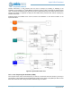
A clock, CLKOUT, generated from any of the oscillators, may be configured and driven onto an external
pin. CLKOUT also drives the Real Time Clock (RTC) Module and other internal clock nodes.
The Clock Generator automatically controls the enabling of the oscillators, so that they are only powered
up and used when requested by another module. This allows minimal power consumption without complex
XT Chain
LFRC Chain
HFRC Chain
CLKOUT
CLKOUT
Core, Flash
100 Hz
XT
Osc
LFRC Osc
HFRC Osc
Calibration
Registers
Module Clocks
Autocal Logic
RTC