
User Manual


Apollo3 Blue Datasheet
DS-A3-0p9p1 Page 456 of 909 2019 Ambiq Micro, Inc.
All rights reserved.
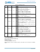
10:9
GPIO10OUT-
CFG
0x0 RW
GPIO10 output configuration.
DIS = 0x0 - FNCSEL = 0x3 - Output disabled
PUSHPULL = 0x1 - FNCSEL = 0x3 - Output is push-pull
OD = 0x2 - FNCSEL = 0x3 - Output is open drain
TS = 0x3 - FNCSEL = 0x3 - Output is tri-state
M3nCE2 = 0x0 - FNCSEL = 0x1 - IOM3 nCE, Channel 2
M4nCE2 = 0x1 - FNCSEL = 0x1 - IOM4 nCE, Channel 2
M5nCE2 = 0x2 - FNCSEL = 0x1 - IOM5 nCE, Channel 2
MSPInCE0 = 0x3 - FNCSEL = 0x1 - MPSI nCE, Channel 0
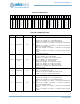
8 GPIO10INCFG 0x0 RW
GPIO10 input enable.
READ = 0x0 - Read the GPIO pin data
RDZERO = 0x1 - INTD = 0 - Readback will always be zero
READEN = 0x1 - INTD = 1 - Read the GPIO pin data
7GPIO9INTD 0x0RW
GPIO9 interrupt direction.
nCELOW = 0x0 - FNCSEL = 0x2 - nCE polarity active low
nCEHIGH = 0x1 - FNCSEL = 0x2 - nCE polarity active high
INTDIS = 0x0 - FNCSEL != 0x2, INCFG = 1 - No interrupt on GPIO transi-
tion
INTBOTH = 0x1 - FNCSEL != 0x2, INCFG = 1 - Interrupt on either low to
high or high to low GPIO transition
INTLH = 0x0 - FNCSEL != 0x2, INCFG = 0 - Interrupt on low to high GPIO
transition
INTHL = 0x1 - FNCSEL != 0x2, INCFG = 0 - Interrupt on high to low GPIO
transition
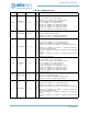
6:5 GPIO9OUTCFG 0x0 RW
GPIO9 output configuration.
DIS = 0x0 - FNCSEL = 0x3 - Output disabled
PUSHPULL = 0x1 - FNCSEL = 0x3 - Output is push-pull
OD = 0x2 - FNCSEL = 0x3 - Output is open drain
TS = 0x3 - FNCSEL = 0x3 - Output is tri-state
M3nCE3 = 0x0 - FNCSEL = 0x1 - IOM3 nCE, Channel 3
M4nCE3 = 0x1 - FNCSEL = 0x1 - IOM4 nCE, Channel 3
M5nCE3 = 0x2 - FNCSEL = 0x1 - IOM5 nCE, Channel 3
M2nCE3 = 0x3 - FNCSEL = 0x1 - IOM2 nCE, Channel 3
4GPIO9INCFG 0x0 RW
GPIO9 input enable.
READ = 0x0 - Read the GPIO pin data
RDZERO = 0x1 - INTD = 0 - Readback will always be zero
READEN = 0x1 - INTD = 1 - Read the GPIO pin data
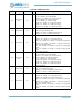
3GPIO8INTD 0x0RW
GPIO8 interrupt direction.
nCELOW = 0x0 - FNCSEL = 0x2 - nCE polarity active low
nCEHIGH = 0x1 - FNCSEL = 0x2 - nCE polarity active high
INTDIS = 0x0 - FNCSEL != 0x2, INCFG = 1 - No interrupt on GPIO transi-
tion
INTBOTH = 0x1 - FNCSEL != 0x2, INCFG = 1 - Interrupt on either low to
high or high to low GPIO transition
INTLH = 0x0 - FNCSEL != 0x2, INCFG = 0 - Interrupt on low to high GPIO
transition
INTHL = 0x1 - FNCSEL != 0x2, INCFG = 0 - Interrupt on high to low GPIO
transition
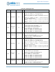
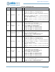
Table 654: CFGB Register Bits
Bit Name Reset RW Description