
User Manual


Apollo3 Blue Datasheet
DS-A3-0p9p1 Page 425 of 909 2019 Ambiq Micro, Inc.
All rights reserved.
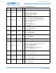
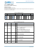
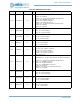
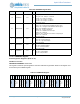
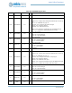
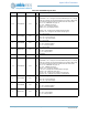
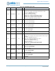
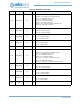
Table 632: PADREGD Register Bits
Bit Name Reset RW Description
31:30 RSVD 0x0 RO
RESERVED
29:27 PAD15FNCSEL 0x3 RW
Pad 15 function select
ADCD1N = 0x0 - Configure as the analog ADC differential pair 1 N input sig-
nal
NCE15 = 0x1 - IOM/MSPI nCE group 15
UART1RX = 0x2 - Configure as the UART1 RX signal
GPIO15 = 0x3 - Configure as GPIO15
PDMDATA = 0x4 - PDM serial data input
SWDIO = 0x6 - Configure as an alternate port for the SWDIO I/O signal
SWO = 0x7 - Configure as an SWO (Serial Wire Trace output)
26 PAD15STRNG 0x0 RW
Pad 15 drive strength
LOW = 0x0 - Low drive strength
HIGH = 0x1 - High drive strength
25 PAD15INPEN 0x0 RW
Pad 15 input enable
DIS = 0x0 - Pad input disabled
EN = 0x1 - Pad input enabled
24 PAD15PULL 0x0 RW
Pad 15 pullup enable
DIS = 0x0 - Pullup disabled
EN = 0x1 - Pullup enabled
23:22 RSVD 0x0 RO
RESERVED
21:19 PAD14FNCSEL 0x3 RW
Pad 14 function select
ADCD1P = 0x0 - Configure as the analog ADC differential pair 1 P input sig-
nal
NCE14 = 0x1 - IOM/MSPI nCE group 14
UART1TX = 0x2 - Configure as the UART1 TX output signal
GPIO14 = 0x3 - Configure as GPIO14
PDMCLK = 0x4 - PDM serial clock output
SWDCK = 0x6 - Configure as the alternate input for the SWDCK input signal
32kHzXT = 0x7 - Configure as the 32kHz crystal output signal
18 PAD14STRNG 0x0 RW
Pad 14 drive strength
LOW = 0x0 - Low drive strength
HIGH = 0x1 - High drive strength
17 PAD14INPEN 0x0 RW
Pad 14 input enable
DIS = 0x0 - Pad input disabled
EN = 0x1 - Pad input enabled
16 PAD14PULL 0x0 RW
Pad 14 pullup enable
DIS = 0x0 - Pullup disabled
EN = 0x1 - Pullup enabled
15:14 RSVD 0x0 RO
RESERVED