
User Manual

Apollo3 Blue Datasheet
DS-A3-0p9p1 Page 406 of 909 2019 Ambiq Micro, Inc.
All rights reserved.
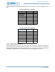
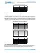
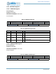
11.5.9 Implementing CLKOUT Connections
The flexible clock output of the Clock Generator module, CLKOUT, may be configured on several pads as
shown in . PADnINPEN and PADnPULL should be cleared in each case.
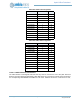
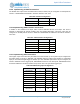
11.5.10Implementing 32kHz CLKOUT Connections
In addition to the CLKOUT mux output, there is also a dedicated 32 kHz clock output. This clock is
primarily for leveraging the 32 kHz oscillator clock from Apollo3 Blue MCU. This clock output may be
configured on several pads as shown in Table 607. PADnINPEN and PADnPULL should be cleared in
each case.
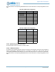
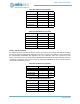
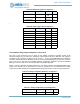
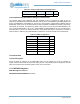
11.5.11Implementing ADC Connections
Three types of pad connections may be made for the ADC module. Up to ten pads may be configured as
the analog inputs, as shown in Table 608. The ADCREF reference voltage input supplied on a dedicated
input pin. If an external digital trigger is desired, up to four selectable pad choices may be configured, as
shown in Table 609. For the trigger inputs, PADnINPEN must be set. For other inputs, PADnINPEN should
be cleared. PADnPULL should be cleared except in the case of an open drain trigger input.
Table 606: CLKOUT Configuration
Field Value Pad
PAD0FNCSEL 2 0
PAD7FNCSEL 2 7
Table 607: 32kHz CLKOUT Configuration
Field Value Pad
PAD14FNCSEL 7 14
PAD24FNCSEL 6 24
PAD33FNCSEL 2 33
PAD36FNCSEL 4 36
PAD47FNCSEL 0 47
Table 608: ADC Analog Input Configuration
Field Value Input Pad
PAD16FNCSEL 0 ADCSE0 16
PAD29FNCSEL 0 ADCSE1 29
PAD11FNCSEL 0 ADCSE2 11
PAD31FNCSEL 0 ADCSE3 31
PAD32FNCSEL 0 ADCSE4 32
PAD33FNCSEL 0 ADCSE5 33
PAD34FNCSEL 0 ADCSE6 34
PAD35FNCSEL 0 ADCSE7 35
PAD13FNCSEL 0
ADCD0M/
SE8
13