
User Manual

Apollo3 Blue Datasheet
DS-A3-0p9p1 Page 405 of 909 2019 Ambiq Micro, Inc.
All rights reserved.
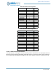
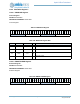
11.5.7 Implementing Secure Card Connections
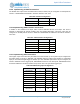
The Secure Card signals can be connected to a variety of pads. Table 603 shows the connections for
Secure Card CLK (SCCCLK), which should have the corresponding PADnINPEN and PADnPULL bits
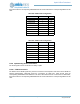
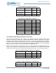
clear. Table 604 shows the connections for Secure Card IO (SCCIO), which must have the corresponding
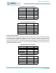
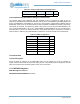
PADnINPEN bit set and should have the corresponding PADnPULL bit clear.Table 605 shows the
connections for Secure Card RSTIO (SCCRST), which must have the corresponding PADnINPEN and
PADnPULL bits clear.
11.5.8 Implementing GPIO Connections
Each pad of the Apollo3 Blue MCU can be configured as a GPIO port by setting PADnFNCSEL to 3.
PADnINPEN and PADnPULL must be set appropriately depending on the specific GPIO function.
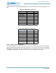
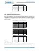
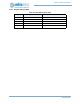
Table 602: I2S DAT Configuration
Field Value Pad
PAD6FNCSEL 7 6
PAD30FNCSEL 7 30
PAD35FNCSEL 4 35
PAD45FNCSEL 4 45
Table 603: Secure Card Clock Configuration
Field Value Pad
PAD8FNCSEL 4 8
PAD17FNCSEL 4 17
PAD19FNCSEL 4 19
PAD31FNCSEL 5 31
Table 604: Secure Card IO Configuration
Field Value Pad
PAD9FNCSEL 4 9
PAD18FNCSEL 7 18
PAD32FNCSEL 4 32
PAD37FNCSEL 4 37
Table 605: Secure Card RST Configuration
Field Value Pad
PAD16FNCSEL 4 16
PAD21FNCSEL 6 21
PAD26FNCSEL 4 26
PAD46FNCSEL 4 46