
User Manual

Apollo3 Blue Datasheet
DS-A3-0p9p1 Page 402 of 909 2019 Ambiq Micro, Inc.
All rights reserved.
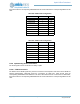
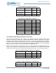
11.5.5.4 UART1 RTS/CTS Connections
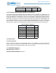
The UART modem control signals RTS and CTS may each be connected to one of two pads. Note that
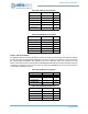
RTS and CTS are selected independently. Table 596 shows the connections for RTS, which should have
the corresponding PADnINPEN and PADnPULL bits clear. Table 597 shows the connections for CTS,
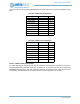
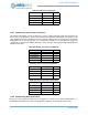
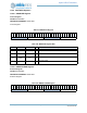
Table 594: UART1 TX Configuration
Field Value Pad
PAD8FNCSEL 6 8
PAD10FNCSEL 0 10
PAD12FNCSEL 7 12
PAD14FNCSEL 2 14
PAD18FNCSEL 6 18
PAD20FNCSEL 5 20
PAD24FNCSEL 0 24
PAD35FNCSEL 2 35
PAD37FNCSEL 5 37
PAD39FNCSEL 1 39
PAD42FNCSEL 0 42
PAD47FNCSEL 6 47
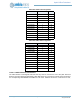
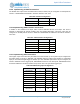
Table 595: UART1 RX Configuration
Field Value Pad
PAD2FNCSEL 0 2
PAD4FNCSEL 5 4
PAD9FNCSEL 6 9
PAD13FNCSEL 7 13
PAD15FNCSEL 2 15
PAD19FNCSEL 6 19
PAD21FNCSEL 5 21
PAD25FNCSEL 0 25
PAD36FNCSEL 2 36
PAD40FNCSEL 1 40
PAD43FNCSEL 0 43
PAD47FNCSEL 6 47