
User Manual

Apollo3 Blue Datasheet
DS-A3-0p9p1 Page 397 of 909 2019 Ambiq Micro, Inc.
All rights reserved.
11.5.3.1 IO Slave I
2
C Connection
I
2
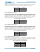
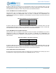
C mode of the IO Slave uses pad 0 as SCL and pad 1 as SDA. This mode is configured by setting the
PADnFNCSEL fields as shown in Table 586. The PAD0INPEN and PAD1INPEN bits must be set.
PAD0PULL and PAD1PULL should be cleared.
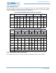
11.5.3.2 IO Slave 4-wire SPI Connection
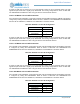
Four-wire SPI mode of the IO Slave uses pad 0 as SCK, pad 1 as MISO, pad 2 as MOSI and pad 3 as
nCE. This mode is configured by setting the PADnFNCSEL fields as shown in Table 587. The
PAD0INPEN, PAD2INPEN and PAD3INPEN bits must be set. PAD0PULL, PAD1PULL, PAD2PULL and
PAD3PULL should be cleared.
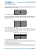
11.5.3.3 IO Slave 3-wire SPI Connection
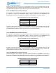
Three-wire SPI mode of the IO Slave uses pad 0 as SCK, pad 2 as MISO/MOSI and pad 3 as nCE. This
mode is configured by setting the PADnFNCSEL fields as shown in Table 588. The PAD0INPEN,
PAD2INPEN and PAD3INPEN bits must be set. PAD0PULL, PAD2PULL and PAD3PULL should be
cleared. Pad 1 may be used for other functions.
11.5.3.4 IO Slave Interrupt Connection
The IO Slave can be configured to generate an interrupt output under a variety of internal conditions. If this
function is used, the interrupt will be generated on pad 4. PAD4FNCSEL must be set to 1, and
PAD4INPEN and PAD4PULL should be cleared.
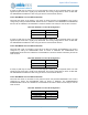
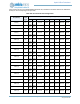
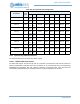
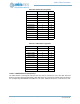
11.5.4 Implementing Counter/Timer Connections
Each Counter/Timer can optionally count pulses from an input pad, or generate pulses on an output pad.
Table 589 shows the PADnFNCSEL settings to connect each Counter/Timer to the appropriate pad. If the
Table 586: IO
Slave I
2
C Configuration
Field Value
PAD0FNCSEL 0
PAD1FNCSEL 0
Table 587: IO
Slave 4-wire SPI Configuration
Field Value
PAD0FNCSEL 1
PAD1FNCSEL 1
PAD2FNCSEL 1
PAD3FNCSEL 1
Table 588: IO
Slave 3-wire SPI Configuration
Field Value
PAD0FNCSEL 1
PAD2FNCSEL 0
PAD3FNCSEL 1