
User Manual

Apollo3 Blue Datasheet
DS-A3-0p9p1 Page 396 of 909 2019 Ambiq Micro, Inc.
All rights reserved.
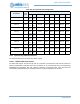
11.5.2 MSPI Connection
The MSPI interface has various device configurations. These are mainly handled within the MSPI
controller configuration. However, there are some additional pad muxing options to provide more flexibility
for system integration. These mux configurations are listed below.
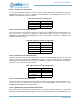
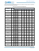
11.5.3 Implementing IO Slave Connections
The IO Master module must be correctly connected to the appropriate pads in order to operate.
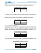
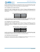
Table 584: MSPI REG_MSPI_PADCFG Input Mux Configuration
Signal
IN0[1:0] IN1 IN2 IN3
3 2 1 0 1 0 1 0 1 0
MSPI0
MSPI
D[5]
MSPI
D[1]
MSPI
D[4]
MSPI
D[0]
-----
MSPI1 - - - -
MSPI
D[5]
MSPI
D[1]
----
MSPI2 - - - - - -
MSPI
D[6]
MSPI
D[2]
--
MSPI3 - - - - - - - -
MSPI
D[7]
MSPI
D[3]
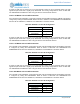
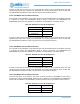
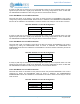
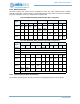
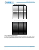
Table 585: MSPI REG_MSPI_PADCFG Output Mux Configuration
Signal
OUT7 OUT6 OUT5 OUT4 OUT3
1 0 1 0 1 0 1 0 1 0
MSPI0 MSPI D[0]
MSPI1 MSPI D[1]
MSPI2 MSPI D[2]
MSPI3 - - - - - - - -
MSPI
CLK
MSPI
D[3]
MSPI4 - - - - - -
MSPI
D[0]
MSPI
D[4]
--
MSPI5 - - - -
MSPI
D[1]
MSPI
D[5]
----
MSPI6 - -
MSPI
D[2]
MSPI
D[6]
------
MSPI7
MSPI
D[3]
MSPI
D[7]
- - ------
MSPI8 MSPI CLK