
User Manual

Apollo3 Blue Datasheet
DS-A3-0p9p1 Page 395 of 909 2019 Ambiq Micro, Inc.
All rights reserved.
A variety of pads may be used for up to four nCE signals to select up to four separate slaves. The nCE
signals are pre-muxed into a signal group called NCE. The muxing configuration is shown in Table 564.
The PADnINPEN and PADnPULL bits of any pad used for nCE should be cleared.
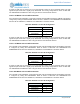
11.5.1.17IO Master 4 3-wire SPI Connection
Three-wire SPI mode of IO Master 4 uses pad 39 as SCK and pad 40 as MOSI/MISO. This mode is
configured by setting the PADnFNCSEL fields as shown in Table 582. The PAD39INPEN and
PAD40INPEN bits must be set. PAD39PULL and PAD40PULL should be cleared. Pad 44 may be used for
other functions.
A variety of pads may be used for up to four nCE signals to select up to four separate slaves. The nCE
signals are pre-muxed into a signal group called NCE. The muxing configuration is shown in Table 564.
The PADnINPEN and PADnPULL bits of any pad used for nCE should be cleared.
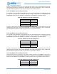
11.5.1.18IO Master 5 3-wire SPI Connection
Three-wire SPI mode of IO Master 5 uses pad 48 as SCK and pad 49 as MOSI/MISO. This mode is
configured by setting the PADnFNCSEL fields as shown in Table 583. The PAD48INPEN and
PAD49INPEN bits must be set. PAD48PULL and PAD49PULL should be cleared. Pad 47 may be used for
other functions.
A variety of pads may be used for up to four nCE signals to select up to four separate slaves. The nCE
signals are pre-muxed into a signal group called NCE. The muxing configuration is shown in Table 564.
The PADnINPEN and PADnPULL bits of any pad used for nCE should be cleared.
11.5.1.19SPI Flow Control Connections
SPI Flow Control in interrupt mode requires an external pin to be specified as the interrupt pin. This is
accomplished by configuring the desired pin in the IOMxIRQ register (x = 0 to 5).
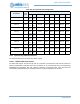
Table 582: IO
Master 4 3-wire SPI Configuration
Field Value
PAD39FNCSEL 5
PAD40FNCSEL 4
Table 583: IO
Master 3-wire SPI Configuration
Field Value
PAD48FNCSEL 5
PAD49FNCSEL 4