
User Manual

Apollo3 Blue Datasheet
DS-A3-0p9p1 Page 391 of 909 2019 Ambiq Micro, Inc.
All rights reserved.
PAD42RSEL and PAD43RSEL fields should be set to select the desired pullup resistor size as shown in
Table 563. If external pullup resistors are used, PAD42PULL and PAD43PULL should be cleared.
11.5.1.5 IO Master 4 I
2
C Connection
I
2
C mode of IO Master 4 uses pad 39 as SCL and pad 40 as SDA. This mode is configured by setting the
PADnFNCSEL fields as shown in Table 570. The PAD39INPEN and PAD40INPEN bits must be set. If the
internal I
2
C pullup resistors are to be used, PAD39PULL and PAD40PULL should be set, and the
PAD39RSEL and PAD40RSEL fields should be set to select the desired pullup resistor size as shown in
Table 563. If external pullup resistors are used, PAD39PULL and PAD40PULL should be cleared.
11.5.1.6 IO Master 5 I
2
C Connection
I
2
C mode of IO Master 5 uses pad 48 as SCL and pad 49 as SDA. This mode is configured by setting the
PADnFNCSEL fields as shown in Table 571. The PAD48INPEN and PAD49INPEN bits must be set. If the
internal I
2
C pullup resistors are to be used, PAD48PULL and PAD49PULL should be set, and the
PAD48RSEL and PAD49RSEL fields should be set to select the desired pullup resistor size as shown in
Table 563. If external pullup resistors are used, PAD48PULL and PAD49PULL should be cleared.
11.5.1.7 IO Master 0 4-wire SPI Connection
Four-wire SPI mode of IO Master 0 uses pad 5 as SCK, pad 6 as MISO and pad 7 as MOSI. This mode is
configured by setting the PADnFNCSEL fields as shown in Table 572. The PAD5INPEN and PAD6INPEN
bits must be set. PAD5PULL, PAD6PULL and PAD7PULL should be cleared.
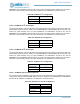
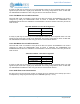
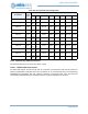
Table 569: IO
Master 3 I
2
C Configuration
Field Value
PAD42FNCSEL 4
PAD43FNCSEL 4
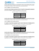
Table 570: IO
Master I
2
C Configuration
Field Value
PAD39FNCSEL 4
PAD40FNCSEL 4
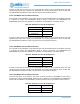
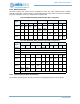
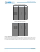
Table 571: IO
Master 5 I
2
C Configuration
Field Value
PAD48FNCSEL 4
PAD49FNCSEL 4
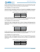
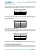
Table 572: IO
Master 0 4-wire SPI Configuration
Field Value
PAD5FNCSEL 1
PAD6FNCSEL 1
PAD7FNCSEL 1