
User Manual


Apollo3 Blue Datasheet
DS-A3-0p9p1 Page 388 of 909 2019 Ambiq Micro, Inc.
All rights reserved.
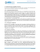
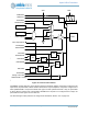
Figure 62. Pad Connection Details
OUTENSEL normally selects a ground signal to keep the pad driver enabled. If the pad is configured to be
Open Drain, the pad enable is driven with the data from the output multiplexer. If the pad is configured as a
GPIO (PADnFNCSEL = 0x3) and the GPIO drive type is tri-state (GPIOnOUTCFG = 0x3), the pad enable
is driven with the inverse of the corresponding GPIOEN bit. If the pad is not configured as an output, the
pad enable is forced high to turn the driver off.
The drive strength of each pad driver is configured as described in Section 11.2 on page 379.
PAD
PADnFNCSEL
AND
GPIOnWT
GPIOnEN
Other Outputs
OUTDATSEL
PADnINPEN
AND
OR
GPIOnRD
PADnFNCSEL = 3
GPIOnINCFG
Other Input Muxes
XOR
INTGPIOnINT
GPIOnINTD
Analog Connection
Mux
PADnSTRNG
AND
PAD
PADnFNCSEL
AND
GPIOnWT
GPIOnEN
Other Outputs
OUTENSEL
OUTDATSEL
PADnINPEN
AND
OR
GPIOnRD
GPIOnINTD
GPIOnINCFG
Other Input Muxes
XOR
INTGPIOnINT
GPIOnINTD
Analog Connection
PADnFNCSEL = analog
PADnPULL
Mux
VDD
PADnRSEL
VDD
PADnSTRNG
AND