
User Manual

Apollo3 Blue Datasheet
DS-A3-0p9p1 Page 380 of 909 2019 Ambiq Micro, Inc.
All rights reserved.
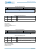
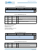
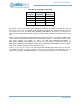
Table 558: Drive Strength Control Bits
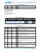
For all pads except for pad 20, REG_GPIO_PADREGy_PADnPULL bit enables a weak pull-up on the pad
when set to one. For pad 20, the REG_GPIO_PADREGy_PAD20PULL bit enables a weak pull-down on
the pad when set to one. The REG_GPIO_PADREGy_PADnINPEN bit must be set to enable the pad
input, and should be left clear whenever the pad is not used in order to eliminate any leakage current in the
pad.
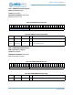
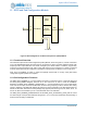
Pads 3 and 36 have selectable high side power switch transistors to provide ~1 Ω switches to VDDH. Pads
37 and 41 have a selectable low side power switch transistors to provide ~1 Ω switches to VSS. The high
side power switches are enabled by setting the REG_GPIO_PADREGF_PAD3PWRUP or
REG_GPIO_PADREGK_PAD36PWRUP bits, and the low side switch is enabled by setting the
REG_GPIO_PADREGB_PAD37PWRDN or REG_GPIO_PADREGB_PAD41PWRDN bit. Once enabled,
the switches operate in parallel with the normal pad function.
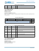
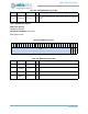
Pads 0, 1, 5, 6, 8, 9, 25, 27, 39, 40, 42, 43, 48 and 49 include optional pull-up resistors for use in I
2
C mode,
to eliminate the need for external resistors. If the pull-up is enabled by the PADnPULL bit, the
REG_GPIO_PADREGy_PADnRSEL field selects the size of the pull-up resistor as shown in Table 563.
ALTPADCFGy_
PADn_DS1
PADREGy_
PADnSTRNG
Nominal Drive
Strength (mA)
002
014
108
1112