
User Manual

Apollo3 Blue Datasheet
DS-A3-0p9p1 Page 362 of 909 2019 Ambiq Micro, Inc.
All rights reserved.
10.2.7 Low Pass Filter (LPF)
The controller’s internal low pass filters attenuate the out-of-band noise at predefined bandwidth and
corners.
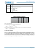
10.2.8 High Pass Filter
The filter response for high pass filter is characterized as:
H(Z) = (1 - Z
1
) / [1 - (1 - 2
-HPGAIN
) Z
-1
]
In default mode, HPGAIN = 1011, so the high pass filter can be formulated by the polynomial:
H(Z) = (1 - Z
1
) / [1 - 0.99951Z
-1
]
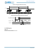
10.3 I2S Slave Interface
The PDM controller supports an optional I
2
S slave interface for PCM serial data output. This enables
support for an external host controller to receive the serial output data from the converted PDM stream. In
I
2
S slave mode, the MSB of I2S_DAT PCM data is available on the second rising edge of I2S_BCLK
following an I2S_WDCLK transition. The other bits up to the LSB are sent in order. The word length is 16
bits so there will be 16 bits of unused I2S_BCLK cycles between the LSB of one sample data and the MSB
of the next one. The I2S_WDCLK is always 32 clock cycles/phase.
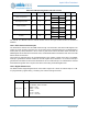
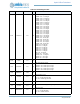
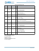
PGA_R[4:0] 0000
Right Channel PGA Gain:
+1.5dB/step, -6dB to +40.5dB
00000 = -6 dB
00001 = -4.5 dB
\u2026
11110 = +39 dB
11111 = +40.5 dB
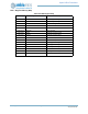
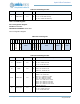
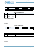
Table 524: LPF Digital Filter Parameters
Parameter Min Typ Max Units
Pass band corner frequency 0.41 Fs
Pass band ripple -1 1 dB
Stop band corner frequency 0.59 Fs
Stop band rejection -60 dB
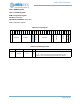
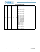
Port Name Default Description