
User Manual

Apollo3 Blue Datasheet
DS-A3-0p9p1 Page 361 of 909 2019 Ambiq Micro, Inc.
All rights reserved.
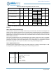
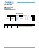
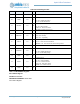
The MCLKL and MCLKR columns indicate whether the left and right channel clocks are enabled or
disabled.
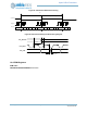
10.2.5 FIFO Control and Interrupts
The PCM data is retrieved from the PDM module through a 32-word FIFO, read at the FRD Register. The
number of words currently in the FIFO (0 to 32) is read in the FR_FIFOCNT field. If the FLUSH Register is
written (with any value) FIFOCNT is set to 0 and any data in the FIFO is discarded. Each read from the
FRD Register will decrement the FIFOCNT value, and FIFOCNT will be incremented each time new PCM
data is written into the FIFO.
There are three interrupts which are generated based on the number of words in the FIFO. The UNDFL
interrupt is generated if software reads from the FRD register when FIFOCNT is 0. The OVF interrupt is
generated if PCM data is received when FIFOCNT is 32. The THR interrupt is set if PCM data is received
and FIFOCNT is greater than or equal to the value in the FTHR_FIFOTHR Register field.
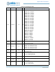
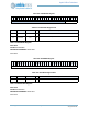
10.2.6 Digital Volume Gain
The PDM controller supports digital volume control with a range from -6 dB to +40.5 dB in steps of 1.5 dB.
It is programmed by register PGA_L and PGA_R for both left and right channels.
Mono Left Unpacked 01 0 N/A
0000 L0
En Dis
0000 L1
Mono Right Unpacked 10 0 N/A
0000 R0
Dis En
0000 R1
Stereo Unpacked 11 0
0
0000 L0
En En
0000 R0
Stereo Unpacked Swapped
11 0 1
0000 R0
En En
0000 L0
Disabled
00 N/A N/A
0000 0000
Dis Dis
0000 0000
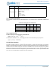
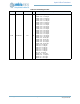
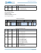
Port Name Default Description
PGA_L[4:0] 0000
Left Channel PGA Gain:
+1.5dB/step, -6dB to +40.5dB
00000 = -6 dB
00001 = -4.5 dB
\u2026
11110 = +39 dB
11111 = +40.5 dB
Table 522: PDM Operating Modes and Data Formats
Mode CHSET PCMPACK LRSWAP 31 - FIFO Data Format - 0 MCLKL MCLKR