
User Manual


Apollo3 Blue Datasheet
DS-A3-0p9p1 Page 360 of 909 2019 Ambiq Micro, Inc.
All rights reserved.
sufficient. However, for voice recording/playback scenarios, this could manifest as pitch/noise problems. In
a scenario where the Apollo3 Blue MCU is used for voice/keyword detect, upon detection, the Apollo3 Blue
MCU can generate notification to the external host. The external host can then send a command to the
Apollo3 Blue MCU to switch clock source.
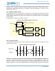
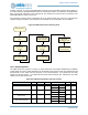
Clock switching requires careful orchestration since the PDM controller will continue to collect/process
samples during this transition. The flow below is an example of how this transition can be handled.
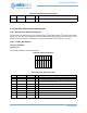
Figure 58. PDM Clock Source Switching Flow
10.2.4 Operating Modes
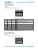
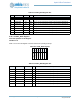
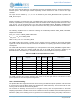
The PDM module can operate in a variety of modes selected by the CHSET, PCMPACK and LRSWAP
register fields, as shown in Table 522 below. The FIFO Data Format column shows the PCM data that will
be presented on each 32-bit read from the FIFO, in two 16-bit segments. “L0” indicates the first 16-bit
sample from the left channel, “L1” indicates the second left channel sample, “R0” indicates the first 16-bit
sample from the right channel, etc.
Table 522: PDM Operating Modes and Data Formats
Mode CHSET PCMPACK LRSWAP 31 - FIFO Data Format - 0 MCLKL MCLKR
Mono Left Packed 01 1 N/A
L1 L0
En Dis
L3 L2
Mono Right Packed 10 1 N/A
R1 R0
Dis En
R3 R2
Stereo Packed 11 1 0
R0 L0
En En
R1 L1
Stereo Packed Swapped 11 1 1
L0 R0
En En
L1 R1
Keyword detect
Interrupt sent to
host
Host sends
command to
Apollo3
MCU disables PDM
MCU sets clock
source to I2S_BCLK
in PDM controller
MCU issue FIFO
flush to PDM
controller
MCU enables PDM
MCU sends interrupt
ack to host
indicating I2S ready
Host uses I2S to
retrieve PCM data