
User Manual


Apollo3 Blue Datasheet
DS-A3-0p9p1 Page 359 of 909 2019 Ambiq Micro, Inc.
All rights reserved.
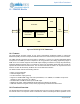
the clock of the internal PDM logic, and therefore the lowest acceptable frequency should be selected to
minimize power. The PDM logic includes separately clocked sections for each of the left and right
channels.
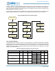
The input clock is divided by 1, 2, 3 or 4 as selected by the PCFG_MCLKDIV field to produce the
PDM_CLKO output.
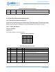
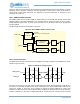
NOTE: If achieving a nominal 50% duty cycle PDM output clock is important, then using a clock divider of
divide-by-3 (MCKDIV3) for PCFG_MCLKDIV should be avoided as the resulting divided clock has a duty
cycle of 67%, not the expected 50%. The other PCFG_MCLKDIV settings, MCKDIV1, MCKDIV2 and
MCKDIV4 can be used to generate an output clock close to 50% duty cycle. See Table 521 for reference.
The following equations are for reference showing the relationship between SINC_RATE, MCLKDIV,
sample rate and OSR.
F
PDM_CLK
= F
S
X 2 X SINC_RATE X MCLKDIV
F
PDM_CLKO
= F
S
X 2 X SINC_RATE
OSR = F
PDM_CLKO
/ F
S
= 2 X SINC_RATE
The PDM module also requires a system clock to operate, which is enabled by the VCFG_IOCLKEN
register bit. This bit should be kept at 0 whenever the PDM is not capturing input data to minimize power
consumption.
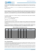
The serial PDM input data is oversampled by a value specified in the PCFG_SINCRATE register field to
produce the PCM data. The resulting PCM data rate is the PDM_CLKO frequency divided by the
SINCRATE value and divided by 2. The table below shows some examples of frequency selection.
The PDM controller also includes separate clock gates for left and right channel. This allows for lower
power operation in mono microphone configuration.
10.2.3 Clock Switching
The Apollo3 Blue MCU supports dual-mode clock sourcing for PDM microphone operation. The first mode
is clock sourcing from the MCU directly (via divided down HFRC reference). The second mode is clock
sourcing from an external host via the I2S_BCLK.
The scenario for switching clock sources is if a higher accuracy clock is required based on the audio
sampling requirements. The MCU clock source is based off of an RC oscillator which has intrinsic jitter that
affects the quality of the resulting clock. For general voice command processing, the quality of the clock is
Table 521: PDM Clock Output Reference Table
F
S
(kHz)
Duty
Cycle (%)
F
PDM_CLKO
(kHz)
OSR MCLKDIV
SYNC_
RATE
Clock Source
7.8125 50 750 96 MCKDIV1 48 750kHz (MCU HFRC)
15.625 50 750 48 MCKDIV1 24 750kHz (MCU HFRC)
15.625 50 1500 96 MCKDIV1 48 1.5MHz (MCU HFRC)
7.8125 67 1000 128 MCKDIV3 64 3MHz (MCU HFRC)
8 50 768 96 MCKDIV1 48 768kHz (external I2S_BCLK)
16 50 768 48 MCKDIV1 24 768kHz (external I2S_BCLK)
16 50 3072 192 MCKDIV4 96 12.288MHz (external I2S BCLK)