
User Manual

Apollo3 Blue Datasheet
DS-A3-0p9p1 Page 358 of 909 2019 Ambiq Micro, Inc.
All rights reserved.
frequency PDM clock is generated to the microphone (requires digital microphone that supports low power
operation). Once a keyword is detected, the MCU generates a wake event to enter normal mode. In
normal mode, higher PDM frequencies are supported to process audio/voice as needed for voice
recording, voice calls, etc.
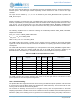
10.2.1 PDM-to-PCM Conversion
The PDM-to-PCM core IP converts PDM bit stream data into 16-bit PCM data through internal data
sampling, filtering, and PGA amplification. The controller may be operated at stereo or mono mode in
normal operation, system reset or power down mode when not in use. Each mode can be programmed
through registers.
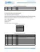
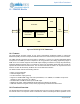
The basic PCM conversion flow is shown in Figure 56.
Figure 56. Stereo PDM to PCM Conversion Path
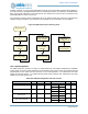
10.2.2 Clock Generation
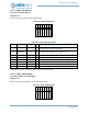
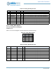
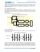
The PDM module generates the clock which is supplied on the PDM_CLKO pin to the PDM source, and is
shown in Figure 57 below.
Figure 57. PDM Clock Timing Diagram
There are two sources for this clock, which are selected by the VCFG_SELAP register bit. If SELAP is 0,
this clock is an internally generated clock which is selected by the VCFG_PDMCLKSEL field and can
range from 12 MHz to 187.5 KHz, and is enabled by setting the PCFG_PDMCLK bit. These clock
selections are derived from the internal 48 MHz HFRC oscillator and therefore will have some frequency
variation. If SELAP is 1, this clock is supplied externally on the I2S_BCLK pin. The input clock is used as
SAMPLER
FIFO
PGA_R
RIGHT PDM-TO-PCM
CONVERTER
LEFT PDM-TO-PCM
CONVERTER
CLOCK
GENERATOR
PDM_CLKO
I2S_BCLK
PGA_L
Internal Source Clock (PDM_CLK)
MCLKR
MCLKL
PDM_IN
LRLR
I
SETUP
I
SETUP
I
HOLD
I
HOLD
PDM_CLKO
PDM_IN