
User Manual

Apollo3 Blue Datasheet
DS-A3-0p9p1 Page 357 of 909 2019 Ambiq Micro, Inc.
All rights reserved.
10. PDM/I2S Module
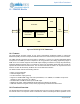
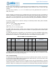
Figure 55. Block Diagram for PDM Module
10.1 Features
The PDM module provides support for low power Pulse-Density Modulated (PDM) to Pulse-Code
Modulated (PCM) conversion and optional I2S slave interface for external host processor communication.
The PDM controller generates the clock output to interface to 1 (mono) or 2 (stereo) PDM-based digital
microphones. The PDM input data is sampled on the rising (left/mono) and falling (right/stereo) edges of
PDM clock. The controller supports 16-bit PCM output sampling at 8/16kHz. The single bit pulse-density
modulated (PDM) bit stream data is converted into pulse-code modulated (PCM) data and provides an
optional I
2
S serial audio/voice data format. The converted PCM data is stored in an asynchronous FIFO
where is can then be retrieved by the MCU CPU via the AHB slave interface.
The PDM controller includes the following features:
▪ Stereo or mono PDM input
▪ 16bit PCM digital output
▪ I
2
S slave interface output (optional)
▪ Support for variable PDM output clock rates (750-768kHz, 1.5-1.536MHz, 3-3.072MHz: output clock
depends on source clock from I
2
S or MCU)
▪ 64x Decimation of PDM bit stream input to PCM output
▪ Sampling rate: 8kHz, 16kHz (additional sample rates are supported as needed)
▪ AHB slave interface for register control, status programming and PCM FIFO data access
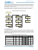
10.2 Functional Overview
The Apollo3 Blue MCU integrates a PDM controller which has two modes of operation: low power mode
and normal mode. The low power mode is intended for wake-on-voice/keyword detect operation. A low
Bus
Interface
REGs
INTs
Decimator
Left PDM-PCM
Conversion
FIFO
IO Mux
Right PDM-PCM
Conversion
I
2
S Controller