
User Manual

Apollo3 Blue Datasheet
DS-A3-0p9p1 Page 341 of 909 2019 Ambiq Micro, Inc.
All rights reserved.
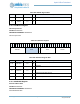
9.13.2.3 FIFOTHR Register
FIFO Threshold Configuration
OFFSET: 0x00000108
INSTANCE 0 ADDRESS: 0x50000108
FIFO Threshold Configuration
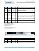
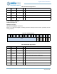
Table 474: FIFOCFG Register Bits
Bit Name Reset RW Description
31:30 RSVD 0x0 RO
RESERVED
29:24 ROBASE 0x20 RW
Defines the read-only area. The IO Slave read-only area is situated in
LRAM at (ROBASE*8) to (FIFOBASE*8-1)
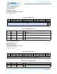
23:16 RSVD 0x0 RO
RESERVED
15:14 RSVD 0x0 RO
RESERVED
13:8 FIFOMAX 0x0 RW
These bits hold the maximum FIFO address in 8 byte segments. It is also
the beginning of the RAM area of the LRAM. Note that no RAM area is con-
figured if FIFOMAX is set to 0x1F.
7:5 RSVD 0x0 RO
RESERVED
4:0 FIFOBASE 0x0 RW
These bits hold the base address of the I/O FIFO in 8 byte segments. The
IO Slave FIFO is situated in LRAM at (FIFOBASE*8) to (FIFOMAX*8-1).
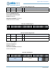
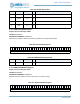
Table 475: FIFOTHR Register
3
1
3
0
2
9
2
8
2
7
2
6
2
5
2
4
2
3
2
2
2
1
2
0
1
9
1
8
1
7
1
6
1
5
1
4
1
3
1
2
1
1
1
0
0
9
0
8
0
7
0
6
0
5
0
4
0
3
0
2
0
1
0
0
RSVD FIFOTHR
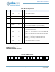
Table 476: FIFOTHR Register Bits
Bit Name Reset RW Description
31:8 RSVD 0x0 RO
RESERVED
7:0 FIFOTHR 0x0 RW
FIFO size interrupt threshold.