
User Manual

Apollo3 Blue Datasheet
DS-A3-0p9p1 Page 338 of 909 2019 Ambiq Micro, Inc.
All rights reserved.
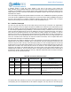
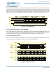
If CPOL is 0, the clock SCK is normally low and positive pulses are generated during transfers. If CPOL is
1, SCK is normally high and negative pulses are generated during transfers.
If CPHA is 0, the data on the MOSI and MISO lines is sampled on the edge corresponding to the first SCK
edge after nCE goes low (i.e. the rising edge if CPOL is 0 and the falling edge if CPOL is 1). Data on MISO
and MOSI is driven on the opposite edge of SCK.
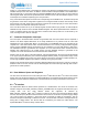
If CPHA is 1, the data on the MOSI and MISO lines is sampled on the edge corresponding to the second
SCK edge after nCE goes low (i.e. the falling edge if CPOL is 0 and the rising edge if CPOL is 1). Data on
MISO and MOSI is driven on the opposite edge of SCK.
The I
2
C/SPI Slave has only a single SPOL bit to control the polarity. If CPOL = CPHA,
REG_IOSLAVE_IOSCFG_SPOL must be set to 0. If CPOL ≠ CPHA, SPOL must be set to 1.
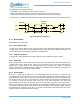
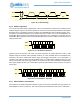
9.11 Bit Orientation
In both I
2
C and SPI modes, the I
2
C/SPI Slave supports data transmission either LSB first or MSB first as
configured by the REG_IOSLAVE_IOSCFG_LSB bit. If LSB is 0, data is transmitted and received MSB
first. If LSB is 1, data is transmitted and received LSB first.
9.12 Wakeup Using the I
2
C/SPI Slave
The I
2
C/SPI Slave can continue to operate even if the Apollo3 Blue MCU CPU is in Sleep or Deep Sleep
mode. The hardware will enable and disable the I
2
C/SPI Slave clock and oscillators as necessary. The
only consideration in this environment is when the MCU is in a deep sleep mode, such that the HFRC
Oscillator is powered down, and a master attempts to access the I
2
C/SPI Slave. In this case the HFRC
Oscillator must be powered up before any is transferred to or from the internal RAM. This process takes
roughly 5-10 us, and is initiated by nCE going low in SPI mode or by the detection of a START in I
2
C mode.
For I
2
C applications, the time delay is typically not relevant. At the fastest system clock of 1 MHz, the
master must transfer 9 bits of address plus 9 bits of offset before any FIFO access can occur, and that is a
minimum of 18 us. The clocks will have started prior to that point in every case.
For SPI applications with fast interface clocks (faster than 1 MHz), the master must be programmed to pull
nCE low at least 10 us prior to sending the first clock. If a master is unable to control the timing of nCE in
this way, then a GPIO interrupt can be configured to wake the Apollo3 Blue MCU prior to initiating any SPI
transfers.
There is no delay restriction if the MCU is in normal Sleep mode. In that case the HFRC is not powered
down and the I
2
C/SPI Slave clock will start immediately when nCE goes low. Alternatively, the FRCHFRC
bit may be set in the FRCHFRC Register in the CLK_GEN module. If this bit is set, the HFRC will continue
to be active even if the Apollo3 Blue MCU CPU is in deep sleep mode, so that the I2C/SPI Slave can
immediately begin transferring data independent of the SPI transfer rate. This will result in higher power
because the HFRC remains active, so the FRCHFRC bit should only be set if it is known that a transfer is
likely to begin prior to another interrupt.
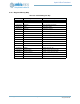
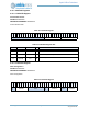
9.13 IOSLAVE Registers
I2C/SPI Slave
INSTANCE 0 BASE ADDRESS:0x50000000