
User Manual

Apollo3 Blue Datasheet
DS-A3-0p9p1 Page 337 of 909 2019 Ambiq Micro, Inc.
All rights reserved.
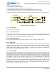
9.10.2 Read Operation
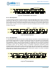
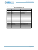
Figure 53 shows a read operation. The address is transferred from the master to the slave just as it is in a
write operation, but in this case the RW bit is a 0 indicating a read. After the transfer of the last address bit
(bit 0), the I
2
C/SPI Slave begins driving data from the register selected by the Address Pointer onto the
MISO line, bit 7 first, and the Address Pointer is incremented. The transfer continues until the master
brings the nCE line high. Note that if the Address Pointer is 0x7F, it does not increment on the read.
Figure 53. SPI Read Operation
9.10.3 Configuring 3-wire vs. 4-wire SPI Mode
The I
2
C/SPI Slave can operate in either 4-wire SPI mode, where the MISO and MOSI signals are on
separate wires, or in 3-wire SPI mode where MISO and MOSI share a wire. This configuration is performed
in the Pin Configuration module, and no configuration is necessary in the I
2
C/SPI Slave itself.
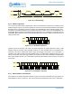
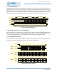
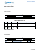
9.10.4 SPI Polarity and Phase
The I
2
C/SPI Slave supports all combinations of CPOL (clock polarity) and CPHA (data phase) in SPI
mode. Figure 54 shows how these two bits affect the interface signal behavior.
Figure 54. SPI CPOL and CPHA
R 6 1
MOSI
SCK
0
Offset Address
nCE
X
Data Byte N Data Byte N+1
7 6 1 0 7 6 1 0
MISO
X
5 4 3 2 5 4 3 2
5 4 3 2
CPOL=0
CPOL=1
7 6 1
MOSI
0 7 6 1 0X 5 4 3 2 5 4 3 2
7 6 1
MISO
0 7 6 1 0X 5 4 3 2 5 4 3 2
SCK
7 6 1
MOSI
0 7 6 1 0X 5 4 3 2 5 4 3 2
7 6 1
MISO
0 7 6 1 0X 5 4 3 2 5 4 3 2
CPHA=0
CPHA=1
X
X
X
X
SCK
nCE