
User Manual


Apollo3 Blue Datasheet
DS-A3-0p9p1 Page 335 of 909 2019 Ambiq Micro, Inc.
All rights reserved.
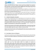
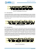
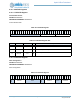
Figure 49. I
2
C Offset Address Transmission
9.9.8 Write Operation
In a write operation the master transmitter transmits to the Apollo3 Blue MCU slave receiver. The Address
Operation has a RW value of 0, and the second byte contains the Offset Address as in Figure 49. The next
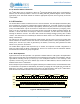
byte is written to the register selected by the Address Pointer (which was loaded with the Offset Address)
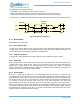
and the Address Pointer is incremented. Subsequent transfers write bytes into successive registers until a
STOP condition is received, as shown in Figure 50. Note that if the Address Pointer is at 0x7F, it will not
increment on the write.
Figure 50. I
2
C Write Operation
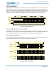
9.9.9 Read Operation
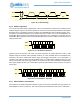
In a read operation, the master first executes an Offset Address Transmission to load the Address Pointer
with the desired Offset Address. A subsequent operation will again issue the address of the Apollo3 Blue
MCU but with the RW bit as a 1 indicating a read operation. Figure 51 shows this transaction beginning
with a RESTART condition, although a STOP followed by a START may also be used. After the address
operation, the slave becomes the transmitter and sends the register value from the location pointed to by
the Address Pointer, and the Address Pointer is incremented. Subsequent transactions produce
successive register values, until the master receiver responds with a NAK and a STOP to complete the
operation. Because the Address Pointer holds a valid register address, the master may initiate another
read sequence at this point without performing another Offset Address operation. Note that if the Address
Pointer is at 0x7F, it will not increment on the read.
Figure 51. I
2
C Read Operation
A1 1 0
SDA
SCL
0 A7 6 1 0
Offset Address
0 1 0 0 5 4 3 2
Addr Offset
SDA
SCL
7 0
Byte N
AWAA 7 0
Byte N+1
A 7 0
Byte N+2
A
SDA
SCL
7 0
Byte N
A A 7 0
Byte N+1
NAddr AR
RESTART
Addr OffsetAW