
User Manual

Apollo3 Blue Datasheet
DS-A3-0p9p1 Page 334 of 909 2019 Ambiq Micro, Inc.
All rights reserved.
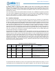
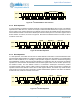
Figure 46. I
2
C Acknowledge
9.9.6 Address Operation
In I
2
C mode, the I
2
C/SPI Slave supports either 7-bit or 10-bit addressing, selected by the 10BIT bit in the
IOSCFG Register. Figure 47 shows the operation in 7-bit mode in which the master addresses the Apollo3
Blue MCU with a 7-bit address configured as 0xD2 in the I2CADDR field. After the START condition, the 7-
bit address is transmitted MSB first. If this address matches the lower 7 bits of the I2CADDR field, the
Apollo3 Blue MCU is selected, the eighth bit indicate a write (RW = 0) or a read (RW = 1) operation and the
Apollo3 Blue MCU supplies the ACK. The Apollo3 Blue MCU ignores all other address values and does not
respond with an ACK.
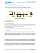
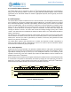
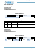
Figure 47. I
2
C 7-bit Address Operation
Figure 48 shows the operation with which the master addresses the Apollo3 Blue MCU with a 10-bit
address configured at 0x536. After the START condition, the 10-bit preamble 0b11110 is transmitted first,
followed by the first two address bits and the eighth bit indicating a write (RW = 0) or a read (RW = 1)
operation. If the upper two bits match the I2CADDR value, the I
2
C/SPI Slave supplies the ACK. The next
transfer includes the lower 8 bits of the address, and if these bits also match I2CADDR the Apollo3 Blue
MCU again supplies the ACK. The I
2
C/SPI Slave ignores all other address values and does not respond
with an ACK.
Figure 48. I
2
C 10-bit Address Operation
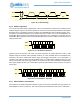
9.9.7 Offset Address Transmission
If the RW bit of the Address Operation indicates a write, the next byte transmitted from the master is the
Offset Address as shown in Figure 49. This value is loaded into the Address Pointer of the I
2
C/SPI Slave.
SDA
SCL
START
MSB (bit 7) Bit 6 Bit 0 ACK
1289
A1 1 0
SDA
SCL
R
W
0 1 0 0
A1 1 0
SDA
SCL
R
W
A1 0 1 11 1 0 1 0 1 1 0