
User Manual


Apollo3 Blue Datasheet
DS-A3-0p9p1 Page 332 of 909 2019 Ambiq Micro, Inc.
All rights reserved.
writing a 1 to the IOINTCLR bit of the IOINTCTL register. This allows the Apollo3 Blue MCU to generate a
software interrupt to the Host device. In addition, a FIFO underflow interrupt FUNDFL in the I2C/SPI Slave
will set interrupt bit 7, and a FIFO read error interrupt FRDERR will set interrupt bit 6 of the IO interrupt
status register IOINT. Note that the Apollo3 Blue MCU software cannot write the IOINTEN register, so that
IO interrupts are controlled completely by the Host processor.
If any of the IOINT interrupt bits are set and the corresponding bit in IOINTEN is set, an IOINT interrupt will
be generated. If the GPIO configuration registers have configured PAD4 as IOINT, that interrupt will be
driven directly onto PAD_IO[4]. This pin should be connected to an interrupt input pin of the Host interface
device so that it can receive the interrupt and service it.
If the Host device writes to any of the interrupt register access locations (any location in 0x78-0x7B) the
IOINTW interrupt will be set in the I2C/SPI INTSTAT Register. This allows Apollo3 Blue MCU software to
receive a software interrupt from the Host device. Note that this interrupt will occur for all writes by the
Host, including a write to clear an interrupt.
9.7 Command Completion Interrupts
Four interrupts in the I2C/SPI Slave module are generated when the Host interface device completes a
transfer. This allows Apollo3 Blue MCU to be easily awakened for any transfer from the Host while
maximizing the time Apollo3 Blue MCU is in sleep mode. The XCMPWR interrupt is generated at the
completion of a Host write transfer which includes addresses in the currently configured Direct Register
space, and the XCMPRR interrupt is generated on the completion of a Host read transfer to that space.
The XCMPWF interrupt is generated at the completion of a Host write transfer which includes the FIFO
address 0x7F (although that is an invalid access), and the XCMPRF interrupt is generated at the
completion of a Host read transfer which includes the FIFO address 0x7F.
NOTE: A write to 0x7F, which is the FIFO address, uses the address 0xFF, since this includes the R/W bit
in the upper (first) bit followed by the 7-bit Direct Register address (offset). The prescribed usage of IOS
FIFO is only for READ from the host, and hence writing to the FIFO is generally an invalid operation. So,
even though XCMPWF flag/interrupt is defined, it is likely never going to be used.
NOTE: A burst transfer which begins in the Direct Register address space and is long enough to cause the
Address Pointer to be 0x7F can set both the Direct Register and FIFO interrupts, although that would in
general be an invalid operation.
9.8 Host Address Space and Registers
The Host of the I/O interface can access 128 bytes in the I
2
C/SPI Slave in either I
2
C or SPI mode. Offsets
0x00 to 0x77 may be directly mapped to the Direct RAM Area. The remaining eight offset locations access
hardware functions within the I
2
C/SPI Slave. The R/W indicator is referring to accesses from the Host.
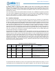
9.9 I
2
C Interface
The Apollo3 Blue MCU I
2
C Slave interface operates as a standard slave. The device is accessed at an
address configured in the REG_IOSLAVE_IOSCFG_I2CADDR field, and supports Fast Mode Plus (up to
1 MHz). Both 7-bit and 10-bit address modes are supported, as selected by
REG_IOSLAVE_IOSCFG_10BIT. The I
2
C interface consists of two lines: one bi-directional data line (SDA)
and one clock line (SCL). Both the SDA and the SCL lines must be connected to a positive supply voltage
via a pull-up resistor. By definition, a device that sends a message is called the “transmitter”, and the
device that accepts the message is called the “receiver”. The device that controls the message transfer by
driving SCL is called “master”. The devices that are controlled by the master are called “slaves”. The
Apollo3 Blue MCU I
2
C Slave is always a slave device.