
User Manual


Apollo3 Blue Datasheet
DS-A3-0p9p1 Page 331 of 909 2019 Ambiq Micro, Inc.
All rights reserved.
If software desires to write the current sample to the front of the FIFO, it first checks the
REG_IOSLAVE_FUPD_IOREAD status bit to ensure that there is not a Host read operation from the FIFO
underway. Once IOREAD is clear, software sets the REG_IOSLAVE_FUPD_FIFOUPD bit, writes the new
sample data to the front of the FIFO and modifies the FIFOPTR to point to the new data. At that point the
FIFOUPD bit is cleared.
If the Host attempts a FIFO read operation while the FIFOUPD is set, a RDERR interrupt will be generated
to the Host and the FRDERR interrupt flag will be set. The Host must either poll the RDERR interrupt bit at
the end of each operation or configure a hardware interrupt. Note that if the software does not support
alternate FIFO ordering, the Host does not have to check the RDERR function.
9.6 Interface Interrupts
The CPU may also signal the Host via the IOINT interrupt, which may be connected to an Apollo3 Blue
MCU pin and driven to the Host. Eight interrupts are available to be combined into the IOINT interrupt, and
the Host can enable, read, clear and set these interrupts via the I/O interface. Software on the CPU can set
6 of the interrupts (SWINT0 through SWINT5) to communicate a variety of situations to the Host, and the
other two interrupts indicate errors such as an attempt by the Host to read the FIFO when it is empty. A
CPU interrupt is generated whenever the Host writes any IOINT registers (for example, to clear an
interrupt) so the CPU can manage the interrupt interaction.The I2C/SPI Slave includes a mechanism to
allow the Host CPU and the Apollo3 Blue MCU to each interrupt the other via a set of eight interrupts. The
Host CPU accesses these interrupts via interface locations 0x78-0x7B, and the Apollo3 Blue MCU
accesses these interrupts in the IOINTCTL Register.
The Host CPU may enable or disable any of the eight interrupts by writing the corresponding bit in the
IOINTEN field of the IOINTCTL Register, which is accessed by the Host at interface location 0x78. The
Host CPU may then clear or set any of the interrupts by writing a 1 to the corresponding bit of the clear (at
location 0x7A) or set (at location 0x7B) registers. The current state of all eight interrupts may be read in the
IOINT field at location 0x79. Note that this structure is identical to the standard Apollo3 Blue MCU
interrupts in all modules. The Apollo3 Blue MCU can read the value of the eight interrupt enables in the
IOINTEN field of IOINTCTL, and can read the values of the eight interrupt status bits in the IOINT field of
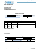
the IOINTCTL register. These two fields are read only. Table 469 summarizes these I/O interface interrupts
and how they can be controlled and read.
The Apollo3 Blue MCU software may set any of the eight interrupt status register bits by writing a 1 to the
corresponding bit of the IOINTSET field of the IOINTCTL Register, and may clear all of the interrupts by
Table 469: I/O Interface Interrupt Control
RAM
Location
IOINT
Register
1
1. Readable by the I/O Host
Function MCU Register_Field Description
0x78 IOINTEN
I/O Interrupt
Enable
IOINTCTL_IOINTEN (R/O)
Each interrupt can be individually enabled by I/O
Host, but can only be read by the MCU
0x79 IOINT I/O Interrupt State IOINTCTL_IOINT (R/O)
State of each interrupt, set or cleared, can be
read by either the I/O Host or by the MCU
0x7A IOINTCLR I/O Interrupt Clear IOINTCTL_IOINTCLR (W/O
Each interrupt can be individually cleared by the
I/O Host, but the MCU can (only) clear all of
them at once
0x7B IOINTSET I/O Interrupt Set
IOINTCTL_IOINTSET (W/
O)
Each interrupt can be individually set by either
the I/O Host or the MCU