
User Manual


Apollo3 Blue Datasheet
DS-A3-0p9p1 Page 327 of 909 2019 Ambiq Micro, Inc.
All rights reserved.
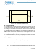
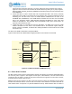
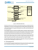
memory locations within the Direct Area and corresponding interrupt bit settings in the REGACCINTSTAT
register.
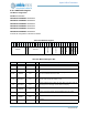
I/O writes to locations 0x0-0xF will set a corresponding interrupt flag in the REGACCINTSTAT register.
These locations are typically used for specific commands to the Apollo3 Blue MCU. Note that not all flags
need generate an actual interrupt, so small multi-byte commands may be transmitted in this area. For
example, a write to location 0x0 will set bit 31 of the REGACCINTSTAT register, a write to location 0x1 will
set bit 30 of REGACCINTSTAT, and a write to location 0xF will set bit 16 of the REGACCINTSTAT register.
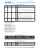
The upper 16 REGACC interrupts are each generated on an access to the last byte of a 32-bit word,
starting at 0x10. I/O writes to locations 0x10 to 0x4F will set a corresponding interrupt flag in the
REGACCINTSTAT register if the I/O address modulo 4 is 3 (i.e. addresses 0x13, 0x17, 0x1B, etc.). This
allows larger transfers to be sent in a burst with a trigger being generated on the last write, and it also
allows
specifyingadatabufferofanywholewordsizeandhaveaninterruptgeneratedonaccesstothe
last byte of the buffer.
For example, a write to location 0x13 will set bit 15 of the REGACCINTSTAT
register, a write to location 0x17 will set bit 14 of REGACCINTSTAT, and a write to location 0x4F will set bit
0 of the REGACCINTSTAT register.
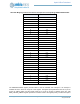
Table 468 lists the offsets to memory locations within the Direct Address Space and corresponding
interrupt bit settings in the REGACCINTSTAT register.