
User Manual


Apollo3 Blue Datasheet
DS-A3-0p9p1 Page 301 of 909 2019 Ambiq Micro, Inc.
All rights reserved.
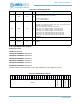
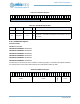
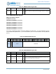
8.15.2.13SUBMODCTRL Register
Submodule control
OFFSET: 0x00000214
INSTANCE 0 ADDRESS: 0x50004214
INSTANCE 1 ADDRESS: 0x50005214
INSTANCE 2 ADDRESS: 0x50006214
INSTANCE 3 ADDRESS: 0x50007214
INSTANCE 4 ADDRESS: 0x50008214
INSTANCE 5 ADDRESS: 0x50009214
Provides enable for each submodule. Only a sigle submodule can be enabled at one time.
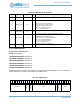
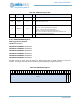
11 DIV3 0x0 RW
Enable divide by 3 of the source IOCLK. Division by 3 is done before the
DIVEN programmable divider, and if enabled
DIS = 0x0 - Select divide by 1.
EN = 0x1 - Select divide by 3.
10:8 FSEL 0x0 RW
Select the input clock frequency.
MIN_PWR = 0x0 - Selects the minimum power clock. This setting should be
used whenever the IOM is not active.
HFRC = 0x1 - Selects the HFRC as the input clock.
HFRC_DIV2 = 0x2 - Selects the HFRC / 2 as the input clock.
HFRC_DIV4 = 0x3 - Selects the HFRC / 4 as the input clock.
HFRC_DIV8 = 0x4 - Selects the HFRC / 8 as the input clock.
HFRC_DIV16 = 0x5 - Selects the HFRC / 16 as the input clock.
HFRC_DIV32 = 0x6 - Selects the HFRC / 32 as the input clock.
HFRC_DIV64 = 0x7 - Selects the HFRC / 64 as the input clock.
7:1 RSVD 0x0 RO
RESERVED
0 IOCLKEN 0x0 RW
Enable for the interface clock. Must be enabled prior to executing any IO
operations.
Table 420: SUBMODCTRL Register
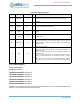
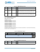
3
1
3
0
2
9
2
8
2
7
2
6
2
5
2
4
2
3
2
2
2
1
2
0
1
9
1
8
1
7
1
6
1
5
1
4
1
3
1
2
1
1
1
0
0
9
0
8
0
7
0
6
0
5
0
4
0
3
0
2
0
1
0
0
RSRVD
SMOD1TYPE
SMOD1EN
SMOD0TYPE
SMOD0EN
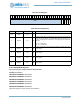
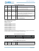
Table 419: CLKCFG Register Bits
Bit Name Reset RW Description