
User Manual

Apollo3 Blue Datasheet
DS-A3-0p9p1 Page 279 of 909 2019 Ambiq Micro, Inc.
All rights reserved.
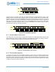
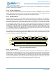
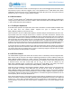
Command is executed with an offset of 10 and a length of 6. This Command will be executed 8 times, each
time bursting 6 bytes of data from registers 10-15 in the peripheral to the I
2
C/SPI Master FIFO. When
CMDCMP is received the FIFO in the I
2
C/SPI Master will contain 48 bytes of data. The bytes of data are
packed in the FIFO – there are no gaps between samples.
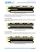
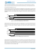
8.10 Bit Orientation
In both I
2
C and SPI modes, the I
2
C/SPI Master supports data transmission either LSB first or MSB first as
configured by the LSB bit in the Command. If LSB is 0, data is transmitted and received MSB first. If LSB is
1, data is transmitted and received LSB first.
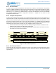
8.11 Full Duplex Operations
Some SPI slaves operate in full duplex mode, where data is transferred on both the MISO and MOSI wires
at the same time. The I
2
C/SPI Master supports this type of operation when the
REG_IOMSTRn_IOMCFG_FULLDUP bit is set.
When FULLDUP is set, the I
2
C/SPI Master splits the standard 128-byte transmit/receive FIFO into a 64-
byte transmit FIFO and a 64-byte receive FIFO. A normal or raw write Command is executed, and
proceeds just as a normal write transfer. FIFOREM will report the remaining FIFO area as the remainder
from 64 bytes. Software must not attempt to load more than 64 bytes into the write FIFO or an IACC error
will be generated. The primary difference from a normal write operation is that data received on the MISO
line will be loaded into the read FIFO, with the bytes aligned to the corresponding byte in the write FIFO.
Software may read the read FIFO at any time, and should use the FIFOSIZ and./or FIFOREM registers to
determine when data should be read. The FIFORTHR threshold value does not generate an interrupt.
If more than 64 bytes of data are written into the read FIFO without being read by software, the read FIFO
will simply wrap around and overwrite the earlier read data. This means that if a long full duplex operation
only returns data at the end, software does not need to continuously empty the read FIFO but can simply
drain the FIFO when the write operation is complete.
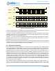
8.12 SPI Flow Control
The I
2
C/SPI Master supports flow control from the slave, which is controlled by several configuration bits.
Either read or write (or both) flow control may be implemented. Read flow control is enabled by setting the
REG_IOMSTRn_IOMCFG_RDFC bit, in which case the I
2
C/SPI Master will check the state of the Flow
Control IRQ pin, and if it is inactive the SPI clock will stop at the completion of the current byte transfer until
it becomes active. The Flow Control IRQ can be any of the 50 pins as selected by the
REG_GPIO_IOMnIRQ register corresponding to the particular I
2
C/SPI Master. The polarity of the active
state of the Flow Control IRQ is selected by the REG_IOMSTRn_IOMCFG_RDFCPOL
Write flow control is enabled by setting the REG_IOMSTRn_IOMCFG_WTFC bit, but in this case either the
Flow Control IRQ or the state of the MISO line may be used for flow control, as selected by the
REG_IOMSTRn_IOMCFG_WTFCIRQ bit. If IRQ is selected by setting a one, the clock control is identical
to that described for reads above and the IRQ polarity is set by the REG_IOMSTRn_IOMCFG_WTFCPOL
bit. If MISO is selected by setting a zero in WTFCIRQ, the clock will be stopped if the MISO line is at the
inactive polarity, which is set by the WTFCPOL bit.
Slave devices supporting flow control typically require specific states of the MOSI line prior to the start of a
transfer. This state is controlled by the REG_IOMSTRn_IOMCFG_MOSIINV bit. If this bit is zero, MOSI will
be driven to a 1 at the start of a write transaction and to a 0 at the start of a read transaction – this is the
normal operation of devices with flow control support. If MOSIINV is set to one, these polarities will be
inverted.