
User Manual

Apollo3 Blue Datasheet
DS-A3-0p9p1 Page 277 of 909 2019 Ambiq Micro, Inc.
All rights reserved.
8.8.7 SPI 3-wire Mode
In 3-wire mode, the MOSI and MISO lines are shared on a single pin. As described in the previous
sections, the MISO and MOSI lines are not driven at the same time, so 3-wire mode is equivalent to simply
tying them together external to the Apollo3 Blue MCU. 3-wire mode is configured by selecting the MxWIR3
alternative (x = 0 to 5 selecting the I2C/SPI Master) in the GPIO Pad Multiplexor rather than the MxMOSI
and MxMISO alternatives. Detailed configuration information is supplied in the GPIO and Pad
Configuration Module chapter.
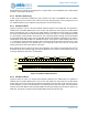
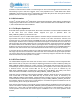
8.8.8 Complex SPI Operations
In some cases peripheral devices require more complex transaction sequences than those supported by a
single Command. In order to support these transactions, the CONT bit may be set in the Command. In this
case, the nCE pin selected by the Channel will remain asserted low at the end of the transaction, so that
the next SPI operation will be seen as part of the same transaction. For example, there are peripheral
devices which require both a Function and an Address Offset to be transmitted at the beginning of a read.
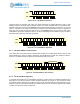
Implementing this can be done in several ways. One example as shown in Figure 36 is:
1. Execute a Raw SPI write of length 2, with the data bytes being the Function and Offset. Set the
CONT bit in this Command so nCE remains asserted low.
2. Execute a Raw SPI Read of the desired transfer length. The data will then be read into the FIFO.
The CONT bit is not set in this Command.
Figure 36. SPI Combined Operation
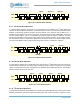
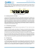
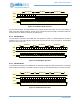
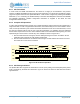
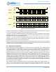
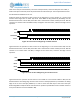
8.8.9 SPI Polarity and Phase
The Apollo3 Blue MCU supports all combinations of CPOL (clock polarity) and CPHA (data phase) in SPI
mode, as defined by the SPOL and SPHA bits. Figure 37 shows how these two bits affect the interface
signal behavior.
7 6 1
MOSI
SCK
0 7 6 1 0
Function
nCE
X
Offset Address
7 6 1 0
Read Data
X
MISO
5 4 3 2 5 4 3 2
5 4 3 2
Raw Write, 2 Bytes Raw Read, 1 Byte