
User Manual

Apollo3 Blue Datasheet
DS-A3-0p9p1 Page 272 of 909 2019 Ambiq Micro, Inc.
All rights reserved.
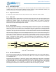
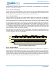
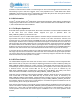
Figure 25. I
2
C 7-bit Address Operation
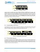
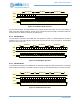
Figure 26 shows the operation with which the master addresses the Apollo3 Blue MCU with a 10-bit
address configured at 0x536. After the START condition, the 10-bit preamble 0b11110 is transmitted first,
followed by the upper two bits of the ADDRESS field and the eighth bit indicating a write (RW = 0) or a read
(RW = 1) operation. If the upper two bits match the address of an attached slave device, it supplies the
ACK. The next transfer includes the lower 8 bits of the ADDRESS field, and if these bits also match
I2CADDR the slave again supplies the ACK. If no slave acknowledges either address byte, the transfer is
terminated and a NAK error interrupt is generated.
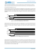
Figure 26. I
2
C 10-bit Address Operation
8.7.7 I
2
C Offset Address Transmission
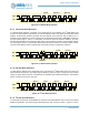
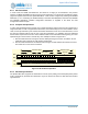
If the OPER field of the CMD selects a Normal Read or Write, the I
2
C/SPI Master will first send an 8-bit
Offset Address byte, where the offset is specified in the OFFSET field of CMD. This transfer is shown in
Figure 27. The Offset Address is loaded into the Address Pointer of the slave.
Figure 27. I
2
C Offset Address Transmission
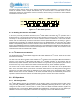
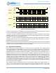
8.7.8 I
2
C Normal Write Operation
In a Normal write operation the I
2
C/SPI Master transmits to a slave receiver. The Address Operation has a
RW value of 0, and the second byte contains the Offset Address, as in Figure 27. The next byte is written
to the slave register selected by the Address Pointer (which was loaded with the Offset Address) and the
Address Pointer is incremented. Subsequent transfers write bytes into successive registers until a STOP
condition is received, as shown in Figure 28.
A1 1 0 1 0 0 0
SDA
SCL
R
W
A1 1 1 1 0 1 0
SDA
SCL
R
W
A1 0 0 1 1 0 1 1
A1 1 0
SDA
SCL
0 A7 6 1 0
Offset Address
0 1 0 0 5 4 3 2