
User Manual

Apollo3 Blue Datasheet
DS-A3-0p9p1 Page 271 of 909 2019 Ambiq Micro, Inc.
All rights reserved.
8.7.2 Start Data Transfer
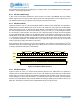
A change in the state of SDA from high to low, while SCL is high, defines the START condition. A START
condition which occurs after a previous START, but before a STOP, is called a RESTART condition, and
functions exactly like a normal STOP followed by a normal START.
8.7.3 Stop Data Transfer
A change in the state of SDA from low to high, while SCL is high, defines the STOP condition.
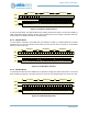
8.7.4 Data Valid
After a START condition, SDA is stable for the duration of the high period of SCL. The data on SDA may be
changed during the low period of SCL. There is one clock pulse per bit of data. Each data transfer is
initiated with a START condition and terminated with a STOP condition. The number of data bytes
transferred between the START and STOP conditions is not limited. The information is transmitted byte-
wide and each receiver acknowledges with a ninth bit.
8.7.5 Acknowledge
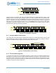
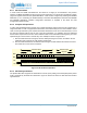
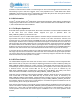
Each byte of eight bits is followed by one acknowledge (ACK) bit as shown in Figure 24. This acknowledge
bit is a low level driven onto SDA by the receiver, whereas the master generates an extra acknowledge
related SCL pulse. A slave receiver which is addressed is obliged to generate an acknowledge after the
reception of each byte. Also, on a read transfer, a master receiver must generate an acknowledge after the
reception of each byte that has been clocked out of the slave transmitter. The device that acknowledges
must pull down the SDA line during the acknowledge clock pulse in such a way that the SDA line is a
stable low during the high period of the acknowledge related SCL pulse. A master receiver must signal an
end-of-data to the slave transmitter by not generating an acknowledge (a NAK) on the last byte that has
been clocked out of the slave. In this case, the transmitter must leave the data line high to enable the
master to generate the STOP condition. If I/O Host attempts an I2C operation but no slave device
generates an ACK, or if a slave fails to generate an ACK on a data byte before the transfer is complete, a
NAK interrupt will be generated.
Figure 24. I
2
C Acknowledge
8.7.6 I
2
C Slave Addressing
For normal I
2
C reads and writes, the Command specifies the address to be sent on the interface. Both 7-
bit and 10-bit addressing are supported, as selected by 10BIT in the Command. The address is specified
in the ADDRESS field.
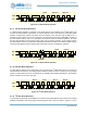
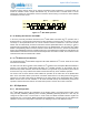
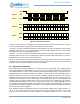
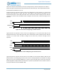
Figure 25 shows the operation in 7-bit mode in which the master addresses the slave with a 7-bit address
configured as 0xD0 in the lower 7 bits of the ADDRESS field. After the START condition, the 7-bit address
is transmitted MSB first. If this address matches the lower 7 bits of an attached slave device, the eighth bit
indicates a write (RW = 0) or a read (RW = 1) operation and the slave supplies the ACK. If no slave
acknowledges the address, the transfer is terminated and a NAK error interrupt is generated.
SDA
SCL
START
MSB (bit 7) Bit 6 Bit 0 ACK
1289