
User Manual


Apollo3 Blue Datasheet
DS-A3-0p9p1 Page 270 of 909 2019 Ambiq Micro, Inc.
All rights reserved.
error interrupt. If software attempts to write the Command Register when another Command is underway
or write the CMD register with a write command when the FIFO is empty (unless the LENGTH field in the
CMD is zero), the Master will generate an ICMD error interrupt.
8.6 FIFO
The I
2
C/SPI Master includes a 64-byte local RAM (LRAM) for data transfers. The LRAM functions as a
FIFO. Only 32-bit word accesses are supported to the FIFO from the CPU. When a write operation is
underway, a word written to the FIFO will increment the REG_IOMSTRn_FIFOPTR_FIFOSIZ register by 4
and decrement the REG_IOMSTRn_FIFOPTR_FIFOREM register by 4. Reading a byte from the FIFO via
the I/O interface decrements FIFOSIZ by 1 and increments FIFOREM by 1. When a read operation is
underway, a word read from the FIFO decrements FIFOSIZ by 4 and increments FIFOREM by 4. A byte
read from the I/O interface into the FIFO increments FIFOSIZ by 1 and decrements FIFOREM by 1. If
FIFOSIZ becomes one during a write operation or 0x40 on a read operation and there is more data to be
transferred, the clock of the I/O interface is paused until software accesses the FIFO.
Two threshold registers, FIFORTHR and FIFOWTHR indicate when a THR interrupt should be generated
to signal the processor that data should be transferred.
8.7 I
2
C Interface
The I
2
C/SPI Master supports a flexible set of Commands to implement a variety of standard I
2
C
operations. The I
2
C interface consists of two lines: one bi-directional data line (SDA) and one clock line
(SCL). Both the SDA and the SCL lines must be connected to a positive supply voltage via a pull-up
resistor. By definition, a device that sends a message is called the “transmitter”, and the device that
accepts the message is called the “receiver”. The device that controls the message transfer by driving SCL
is called “master”. The devices that are controlled by the master are called “slaves”. The Apollo3 Blue MCU
I
2
C Master is always a master device.
The following protocol has been defined:
▪ Data transfer may be initiated only when the bus is not busy.
▪ During data transfer, the data line must remain stable whenever the clock line is high.
▪ Changes in the data line while the clock line is high will be interpreted as control signals.
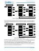
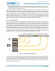
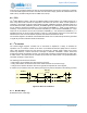
A number of bus conditions have been defined (see Figure 23) and are described in the following sections
Figure 23. Basic I
2
C Conditions
8.7.1 Bus Not Busy
Both SDA and SCL remain high.
SDA
SCL
START SDA Stable
SDA may
change
STOP
Not Busy