
User Manual


Apollo3 Blue Datasheet
DS-A3-0p9p1 Page 262 of 909 2019 Ambiq Micro, Inc.
All rights reserved.
8.2.3 FIFO
The IOM module contains 2 uni-directional FIFOs, each 32 bytes wide. These FIFOs are used only for data
storage during IO transactions. The FIFO supports both single (half duplex) and duplex modes of
operation.
During direct mode data transfer operations, IO data transfer between the IOM module and the MCU is
done by accessing the REG_IOM_FIFOPOP and REG_IOM_FIFOPUSH registers. These registers allow
read (FIFOPOP) and write (FIFOPUSH) of data into and out of the FIFO, and automatic adjustment of
pointers used by the submodules. Only word accesses are permitted to these registers and any unused
byte locations will be ignored or filled with zero. If DMA is enabled during the IO command operation, data
will automatically be read or written into the FIFO from the DMA address and the pointers updated. The
FIFO pointers and data are NOT reset after each command, and care must be taken to not leave any extra
data in the FIFO, as this will be used for subsequent transfers. If needed, there is a manual reset of the
FIFO pointers that can be done using the REG_IOM_FIFOCTRL.FIFORSTN field. Additional information
on data alignment is covered in the later sections of this document.
The submodules will prevent overruns or underruns from the FIFO by pausing the active transaction,
usually by stopping the output clock. Once data is available (write operations) or there is room in the FIFO
(read operations), the transaction will continue.
For debug operations, the IOM module also allows direct access to the FIFO contents through the
REG_IOM_FIFO aperture. Access via this path does not affect the pointers used by the submodules and
cannot be used to send or receive data as part of the IO operation. The FIFO aperture allows read and
write operations into the write FIFO and read access into the read FIFO. The current FIFO pointers are
readable via the FIFOLOC register. For the write FIFO, this will point to the next location to be written,
while the read FIFO pointer will indicate the next location to be read.
FIFO ACCESS NOTE: When DMA operations are in progress, the FIFOPUSH and FIFOPOP registers
should not be accessed, as this will interfere with the DMA data.
8.2.4 Data Alignment
All data accesses between the MCU and the IOM interface are word aligned. Since the transfer size is
specified in bytes, unused bytes within the word will either be discarded (for write operations) or filled with
zero (read operations) to align to the next word boundary. DMA operations support a byte starting address,
and the programmed DMA address does not have to be word aligned. Direct mode write operations will
start transferring the least significant byte of the word (little endian style) at the current write FIFO pointer.
If any remaining bytes are unused in a word at the end of the write operation, they will be discarded, and
the write pointer will be set to the next word location. Direct mode read operations will store the first
received byte into the least significant byte of location specified by the read FIFO pointer, and will fill any
unused byte locations with zero if the transaction size is not a word multiple. The FIFO read pointer will
point to the next FIFO location in the read FIFO, which will be word aligned.
8.2.4.1 Direct Mode Data Transfers
Direct mode data is enabled when DMA is disabled via the REG_IOM_DMACFG.DMAEN and the data
transfer size (TSIZE) is greater than 0. In this mode, the MCU transfers data via direct writes or reads to
registers in the IOM. The IOM maintains separate FIFO pointers for the read and write FIFOs, and updates
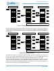
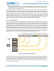
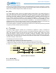
these when a PUSH or POP register is accessed. Writing to the REG_IOM_FIFOPUSH register will
perform a push event of the word into the FIFO and update the write pointer by 4 bytes. Only word
accesses are supported to the IOM, and any unused bytes within a word will be discarded. An example of
a 5 byte write transfer is shown below.