
User Manual


Apollo3 Blue Datasheet
DS-A3-0p9p1 Page 261 of 909 2019 Ambiq Micro, Inc.
All rights reserved.
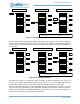
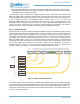
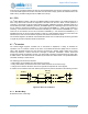
Figure 16. IO_CLK Generation
The divided by 3 divider is optional and will provide a 50% duty cycle divided by 3 clock. This divider is
bypassed when the DIV3 field is set to 0.
The output of the DIV3 module is then fed to the programmable divider. This divider can be bypassed or
enabled via the DIVEN field in the CLKCFG. It will divide at a rate of TOTPER+1 (subtract 1 from actual
value when writing TOTPER field), and will toggle at LOWPER+1 clock count of the base IO_CLK from the
DIV3 module. This will generate the final IO_CLK used by the interface module.
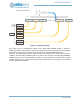
8.2.2.1 I2C Clock Generation
The I
2
C output clock (SCL) is derived from dividing the final IO_CLK by 2. For example, for 1Mhz I
2
C
operation, an IO_CLK frequency of 2Mhz is required. Because the state machine will operate at 2x the
target frequency of the interface frequency, the nominal output clk (SCL) duty cycle will be 50%, regardless
of the duty cycle of the IO_CLK. However, the timing specification of some I
2
C modes require an
asymmetrical duty cycle on the SCL output, with the high period of the clock less than the low period of the
clock. The clocking module allows a programmable delay prior to propagating the rising edge of the SCL
output. This delay is in units of the source IO_CLK period (prior to any enabled division). This delay is
specified in the REG_IOM_MI2CCFG.SCLENDLY register field. The recommended settings for this
register for each mode are detailed below.
If clock stretching is done by the slave devices attached to the IOM interface, further restrictions must be
observed during the setup of the clock controls. This is due to the possible clock stretch event done within
a single cycle on the I
2
C SCL. In this case, the minimum SCL high time must be maintained, regardless of
the time the slave releases the SCL. To detect the event within the single I
2
C cycle, the SCL signal needs
to be sub-sampled. The source IO_CLK is used for this purpose also and allows for sampling of the SCL
signal by a programmable number of source IO_CLK cycles. The sample granularity is determined by the
ratio of the source IO_CLK to final IO_CLK frequency and must allow for synchronization time between the
two domains. The recommended settings for each mode are below. Only speeds of 100KHz, 400KHz and
1MHz are supported. Contact Ambiq Micro for use of other frequencies. are highlighted for each mode.
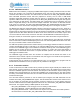
Table 394: Recommended Mode Settings for Standard I2C Clock Speeds
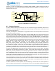
8.2.2.2 SPI Clock Generation
The final IO_CLK is used directly as the SPI clock output. No additional settings are needed.
Mode FSEL DIV3 DIV EN
TOT
PER
LOW
PER
SMP
CNT
SDAEN
DLY
SCLEN
DLY
Standard Mode
(100 KHz)
3 0 160393150
Fast Mode
(400 KHz)
2 0 1 31 19 15 15 2
Fast Mode+
(1000 KHz)
30163130