
User Manual


Apollo3 Blue Datasheet
DS-A3-0p9p1 Page 259 of 909 2019 Ambiq Micro, Inc.
All rights reserved.
8.1.1 Main Features
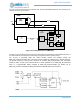
No resources are shared between IOM modules, but within a single IOM module, the submodules share a
common set of FIFO and command resources.
8.1.1.1 Features common to all submodules
- 2 Independent 32-byte FIFOs, one dedicated each direction of data transfer
- Direct access of all FIFO data from MCU interface, including non-destructive reads.
- FIFO mode read/write access (push/pop mechanism)
- Direct command, direct data mode. (Command and data written to/read from the module registers
directly)
- Direct command, DMA data mode. Commands are written directly to the module, but data is written to/
read from the main SRAM array.
- Command queuing operations. Registers write operations are read from main SRAM memory and fed
to the register unit in series.
- Programmable interrupts
- Programmable threshold interrupt level
- Configurable clock selection
- Read data synchronized internally for MCU access
- Ability to send multi-byte offset addresses, with single command
- Ability to view FIFO data without causing pop operation
- Capability to store data for multiple commands in either FIFO
- Programmable number of byte offsets of 0-3
8.1.1.2 I2C Master features
- Support for standard mode (100KHz), Fast mode (400KHz), and Fast mode+ (1MHz)
- Support for 7b and 10b addressing modes
- Transfer burst sizes of 0 to 255 bytes.
- Configurable LSB or MSB data transfer.
- Clock stretching support.
8.1.1.3 SPI Master features
- Support for transaction sizes up to 4095 bytes
- Programmable number of byte offsets of 0-3
- Programmable operation in all polarity modes
- 3-wire and 4-wire read and write support
- Flow control for reads or writes, based on MISO (write flow control), or external, selectable PIO.
- Full duplex operation
8.2 Functional Description
8.2.1 Power Control
The 6 IOM modules are separated into 2 power domains, referred to as HPCB and HCPC. IOM modules
0,1 and 2 are contained in HCPB, while IOM modules 3,4 and 5 are contained in HCPC power domain.
The power domain must be enabled in the REG_PWRCTRL_DEVPWREN register prior to access and
operation.
8.2.2 Clocking and Resets
The IOM design uses 2 main clocks, APB_CLK and IO_CLK. The APB_CLK is used for all register and
DMA accesses. It runs at 24Mhz and will be interfaced via the APB fabric synchronous interface. The