
User Manual

Apollo3 Blue Datasheet
DS-A3-0p9p1 Page 225 of 909 2019 Ambiq Micro, Inc.
All rights reserved.
7.6.5 MSPI and IOM Intercommunication
The MSPI module and IOM modules can be linked through the command queue flags to allow a simple
form of handshaking to facilitate data flow between the two modules. The MSPI only has a single pair of
hardware flags dedicated to IOM communication so software must write the IOMSEL field in the MSPICFG
register to select which IOM is paired with the MSPI.
A typical use model for this feature is for transmitting blocks of data stored in external flash to a device
(such as a display) on the IOM interface. In this scenario, software would allocate two buffers in SRAM
which would be filled by the MSPI and emptied by the IOM. At the beginning of the operation, software
would clear the IOM0START and IOM1START flags and initialize the MSPI command queue with two read
operations to load data into buffer 0 and buffer 1. Software would also initialize the corresponding flags in
the IOM and set up the IOM command queue to point to begin reading at buffer 0, but pause the IOM until
it sees the buffer0 status is ready.
When the MSPI command queue is enabled, it will check the IOM0READY flag (which will be zero since
the incoming bit is zero and the IOM0START flag is zero) and begin processing the operation which would
DMA data from the external flash to fill buffer 0. At the end of the operation, the CQ would write the
CQPAUSE register with the mask for IOM1READY. The status of IOM1READY will also be zero, so it will
continue processing to fill buffer 1. At the end of this operation, the CQ will write the CQPAUSE register to
IOM0READY again, but this time it will likely pause because the IOM is still reading data out of buffer 0.
Once the IOM finishes its reads from buffer 0, it's CQ will set the flag for buffer 0, which will in turn cause
the IOM0READY hardware flag to become zero and allow the MSPI to continue processing (which would
fill buffer 0 again). In this manner, software would only need to continue adding commands to the MSPI
command queue in order to continuously feed data frames to the IOM device.
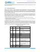
7.7 Data Scrambling
In order to protect customer data stored on external flash devices, the MSPI module supports a data
scrambling algorithm to obfuscate data on the MSPI bus. Scrambling can be enabled by programming the
SCRSTART and SCREND registers to correspond to the address range to be encrypted and setting the
SCRENABLE bit in the CFG register. Scrambling is enabled for all DMA and XIP operations that fall within
the scrambling window.
Accesses to the scrambling region must always be to an aligned, four-byte boundary (i.e. device address
must always end in 0x0, 0x4, 0x8, 0xC). Accesses through the XIP region are always aligned to cache
lines, but software must ensure that DMA operations are properly aligned. In the case of a mis-aligned
DMA access, the MSPI will issue the SCRERR interrupt (SCRambling ERRor).
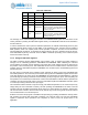
7.8 Auto Power Down
The MSPI module has the ability to power itself down at the end of a DMA or CQ operation. This would
usually be done while the system is going into deep sleep but desires the MSPI to transfer data to or from
a flash device during the beginning of the sleep period. To enable auto-power down, software should
enable the DMA with the DMAPWROFF bit set or command queuing with the CQPWROFF bit set.
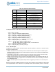
7.9 Pad Configuration and Enables
The MSPI transfer block generally handles the bit/byte alignment for transfers, but the MSPI also provides
a set of internal pin muxes controlled by the PADCFG register to provide system level designers more
options when connecting flash devices by allowing the association of chip enable with a mixture of data
pins - for instance, chip enable 1 may be used in a quad configuration with data pins 0, 1, 6, 7 of the SPI
interface. The pin muxing also controls the separation of I/O operations for serial devices or transfer
modes, where pin 0 is typically MOSI and pin 1 is MISO instead of being a shared tristate pin.