
User Manual


Apollo3 Blue Datasheet
DS-A3-0p9p1 Page 223 of 909 2019 Ambiq Micro, Inc.
All rights reserved.
This can be useful when software would like intermediate interrupts as operations complete such as after
each CQ index is updated.
7.6.3 Pausing CQ Operations
While the basic operation of the CQ functionality is pretty straightforward, constructing more complex
scenarios such as queuing of multiple operations requires additional logic to accommodate handshaking
with the software managing the queue and other modules within the chip. The MSPI accomplishes both of
these by providing the ability to pause the CQ processing using a pause mask (CQPAUSE register) and
software and hardware pause flags.
After the MSPI executes a CQ write operation, it will check all bits specified in the CQPAUSE register
against their CQFLAGS status, and will pause operation if all of the associated CQFLAGS bits are set.
Since all registers are available to be written by both CPU software and CQ commands, there are
numerous ways these can be used, but two common scenarios are
▪ Software can initially set a mask in CQPAUSE and CQ operation will continue until the matching
CQFLAGS condition is encountered.
▪ The CQ command stream can set the CQPAUSE register during execution and pause until the status in
FLAGS changes to indicate that it should restart.
The CQFLAGS register contains 8 soft flags (register bits that can be controlled by either the CPU or the
QC operation) and an additional 8 hard flags, which are hardware status flags tied to logic in the MSPI
module or other modules in the chip. The lowest two soft flags are also exported to the IOM SPI modules
to facilitate communication between an IOM and the MSPI to enable management of common MSPI/IOM
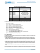
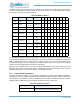
buffers via the command queues. The table below lists the flags available in the MSPI:
Table 324: CQFLAGS
Bit Type Mnemonic Description/Use
15 Hard STOP
CQ Stop Flag. When set to 1, CQ process-
ing will terminate and the CQCPL interrupt
will be generated.
14 Hard CQIDX
CQ Index Pointer Match. Will be set to 1
when the CURIDX and ENDIDX pointers
match. Generally used by software when
forming a request queue.
13 Hard Reserved
12 Hard Reserved
11 Hard Reserved
10 Hard Reserved
9 Hard IOM1READY
IOM Buffer 1 Ready Status. This hardware
bit represents the XOR of the soft
IOM1START with the incoming IOM1 ready
status bit and indicates that buffer 1 has
been emptied by the IOM.
8 Hard IOM0READY
IOM Buffer 0 Ready Status. This hardware
bit represents the XOR of the soft
IOM0START with the incoming IOM0 ready
status bit and indicates that buffer 0 has
been emptied by the IOM.
7 Soft SWFLAG7 Software flag
6 Soft SWFLAG6 Software flag